SW1 -2 OFF = Green LED lit when +24 present on TBl-7.
Red LED lit when +24 absent from TBl-7.
SW1 -2 ON = Green LED lit when SW3 in ON position.
Red LED lit when SW3 in OFF position.
Switches SWl-3 and SW1-4 (Functions depend on whether or not the 4002 has ESP.)
If the panel
lacks
ESP, the module responds to the issuance of any alarm message as follows:
SWl-3
SW1 -4
ON
ON =
Leaves fans in their current state.
ON
OFF =
Turns both fan circuits OFF.
OFF ON =
Turns both fan circuits ON.
OFF
OFF =
Turns fan circuit 1 ON, turns fan circuit 2 OFF.
If the panel has ESP, switches SW1 -3 and SW1 -4 identify the fans under the module’s control as follows:
SW1 -3
SW1 -4
ON
ON =
Module controls fans 1 and 2.
ON
OFF =
Module controls fans 3 and 4.
OFF ON =
Module controls fans 5 and 6.
OFF
OFF =
Module controls fans 7 and 8.
Note: ESP allows the CPU to turn individual fans ON or OFF, depending on which of the system’s zones
is in alarm.
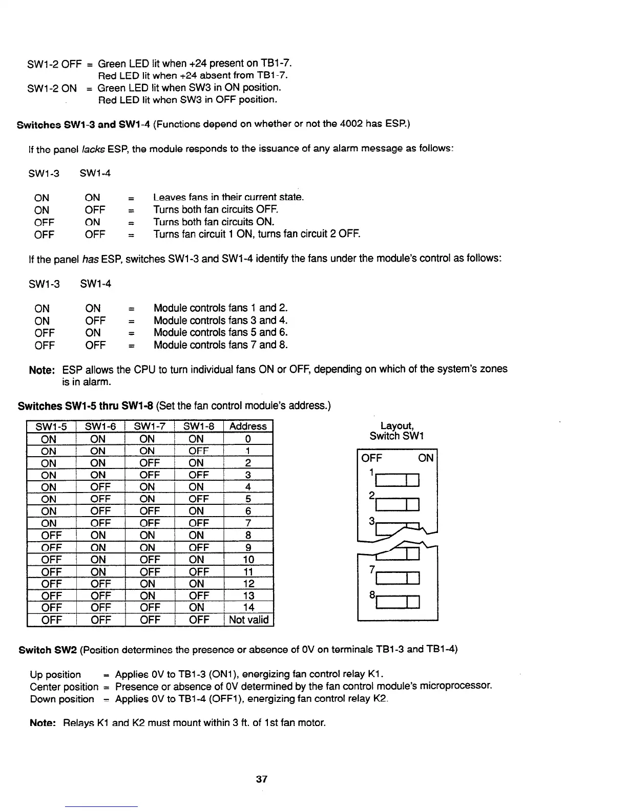
Switches SWl-5 thru SW1-8 (Set the fan control module’s address.)
SW1 -5
ON
l3N
urr I
OFF j ON
h
I
-. -
+
ON
oi ---
ON
ON
OFF 1
OFF /
3
I
ON
OFF ON I ON
4
I
1
ON
1 OFF 1 ON
1 OFF /
5
I
Layout,
Switch SW1
I
OFF
ON
Switch SW2 (Position determines the presence or absence of OV on terminals TBl-3 and TBl-4)
Up position
= Applies OV to TBl-3 (ONl), energizing fan control relay Kl .
Center position = Presence or absence of OV determined by the fan control module’s microprocessor.
Down position
= Applies OV to TBl-4 (OFFl), energizing fan control relay K2.
Note: Relays Kl and K2 must mount within 3 ft. of 1st fan motor.
37
Technical Manuals Online! - http://www.tech-man.com