l
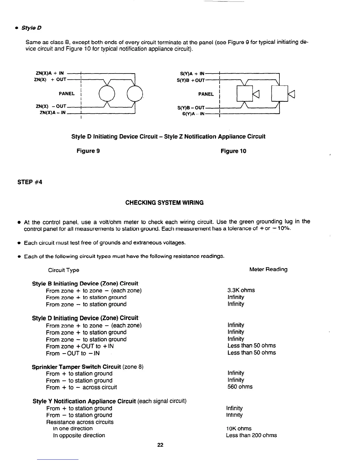
Style D
Same as class B, except both ends of every circuit terminate at the panel (see Figure 9 for typical initiating de-
vice circuit and Figure 10 for typical notification appliance circuit).
ZN(X)A + IN
I
ZN(X) + OUT
1
I
PANEL 1
ZW)
- OUT
I
1
ZN(X)A - IN
I
I
S(Y)A + IN
I
S(Y)B +OUT
I
PANEL
I
I
S(Y)B - OUT
)
S(Y)A - IN
I
Style D Initiating Device Circuit - Style Z Notification Appliance Circuit
Figure 9
Figure 10
STEP #4
CHECKING SYSTEM WIRING
l
At the control panel, use a volt/ohm meter to check each wiring circuit. Use the green grounding lug in the
control panel for all measurements to station ground. Each measurement has a tolerance of + or - 10%.
l
Each circuit must test free of grounds and extraneous voltages.
l
Each of the following circuit types must have the following resistance readings.
Circuit Type
Meter Reading
Style B Initiating Device (Zone) Circuit
From zone + to zone - (each zone)
From zone + to station ground
From zone
- to station ground
3.3K ohms
Infinity
Infinity
Style D Initiating Device (Zone) Circuit,
From zone + to zone - (each zone)
From zone + to station ground
From zone
- to station ground
From zone + OUT to + IN
From -OUT to - IN
Infinity
Infinity
Infinity
less than 50 ohms
Less than 50 ohms
Sprinkler Tamper Switch Circuit (zone 8)
From + to station ground
From
- to station ground
From + to - across circuit
Infinity
Infinity
560
ohms
Style Y Notification Appliance Circuit (each signal circuit)
From + to station ground
From - to station ground
Resistance across circuits
In one direction
In opposite direction
Infinity
Infinity
1 OK ohms
Less than 200 ohms
22
Technical Manuals Online! - http://www.tech-man.com