SECTION 2
__ ..-...-------.-. ._ _--- _... ---..- .-
CAUTION
I
NEVER REMOVE OR REPLACE CABLES OR WIRES WITH POWER APPLIED TO THE SYSTEM
!
1
To power down the system:
1. Disconnect either of the battery’s terminals.
/
2 Turn off system power at the AC breaker.
!---------_-_-.-- ..--- --
To power up the system:
1. Turn on system power at the AC breaker.
2 Apply battery power.
1
I
I
INSTALLATION INSTRUCTIONS
INTRODUCTION
This section provides both information and instructions on the 4002 fire alarm system wiring. It is important that
you read this section and utilize the 4002 field wiring diagrams 841-669 and 841-687 which accompany the control
panel to install your fire alarm system.
l
To help you in the installation of this and other Simplex fire alarm systems, the following publication has been
made available for general reference: How to Wire a Building for a Fire Alarm System (Simplex Publication
No. FA2-91-001).
General Notes
a. When running wires to the control panel, identify and tag all wires appropriately: 120 VAC or 220/240 VAC
power; signal circuit 1; zone 1, zone 5 etc.; and identify all “+” and ‘I-” wires by color code or numerical sequence.
b. The panel’s terminal strips are labeled with a terminal strip number (TBl, TB2, etc.), and each terminal is
designated by a terminal number (1, 2, 3, etc.). Therefore, TBl-1 is terminal 1 on terminal strip 1, TB3-2 is
terminal 2 on terminal strip 3, etc. In addition, each terminal is identified by an abbreviation of the circuit
function to be connected. For example, zone 1 = ZNl +, ZNl -, signal circuit 2 = S2B + , S2B - ; annunciator
output from zone 5 = ANN 5 - .
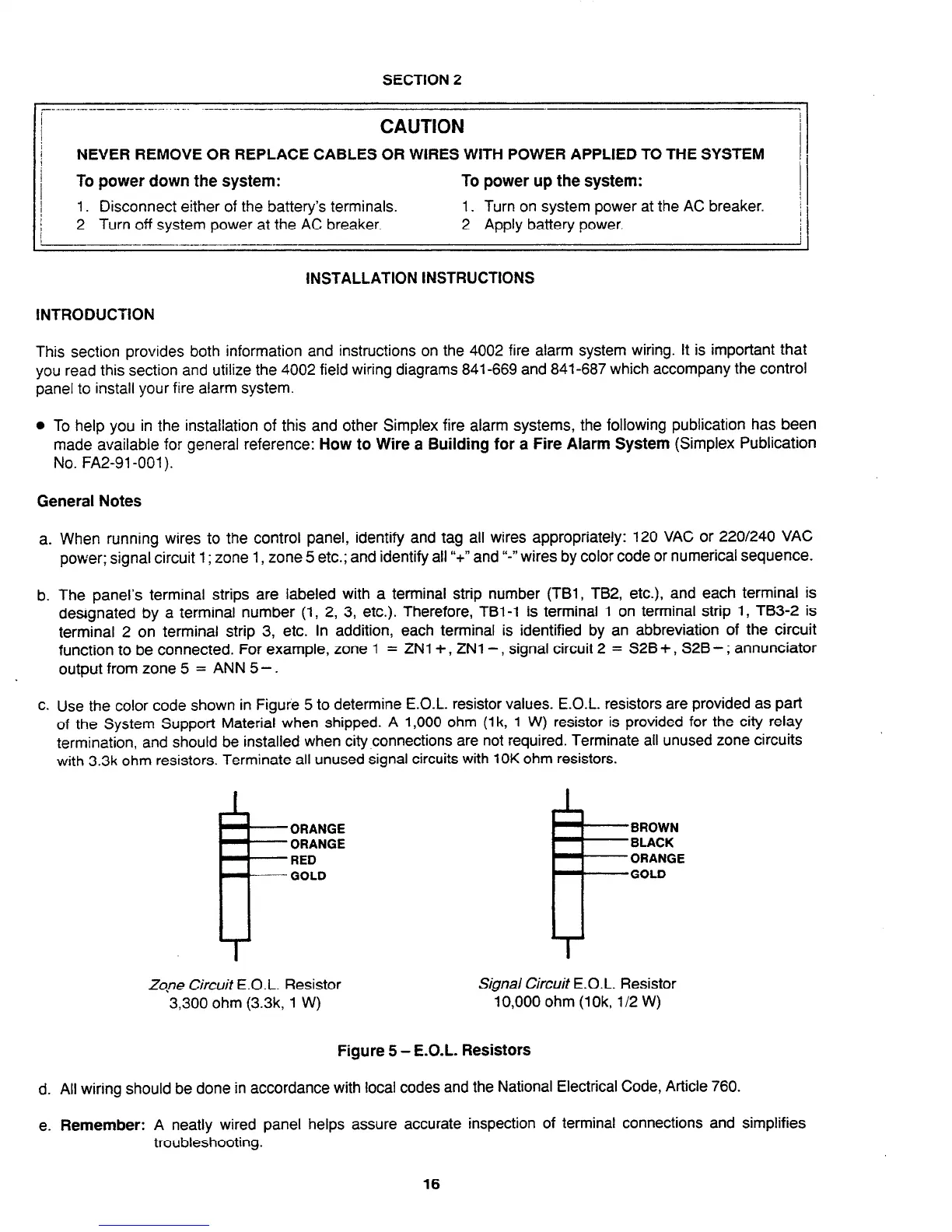
c. Use the color code shown in Figure 5 to determine E.O.L. resistor values. E.O.L. resistors are provided as part
of the System Support Material when shipped. A 1,000 ohm (1 k, 1 W) resistor is provided for the city relay
termination, and should be installed when city connections are not required. Terminate all unused zone circuits
with 3.3k ohm resistors. Terminate all unused signal circuits with 10K ohm resistors.
k-
ORANGE ORANGE
ORANGE ORANGE
RED RED
GOLD GOLD
BROWN BROWN
BLACK BLACK
ORANGE ORANGE
GOLD GOLD
Zqne Circuit E.O.L. Resistor
Signal Circuit E.O.L. Resistor
3,300 ohm (3.3k, 1 W)
10,000 ohm (lOk, l/2 W)
Figure 5 - E.O.L. Resistors
d. All wiring should be done in accordance with local codes and the National Electrical Code, Article 760.
e. Remember: A neatly wired panel helps assure accurate inspection of terminal connections and simplifies
troubleshooting.
16
Technical Manuals Online! - http://www.tech-man.com