4100U-S1 Programming Guide Document: LT0400
Adding Expansion Modules
Page 8-2 15 December 2010 Issue 1.4
8.1 General
See Installation manual LT0394 Iss1.4 Chapter 2 for Physical requirements of fitting cards in
bays.
This section describes the procedure to configure the panel with additional modules which
may be added to the panel. It describes the concept and method of adding modules by
giving detailed examples of 6 cards: IDNet, 6 Supervised Signal Card, 8 Point Monitor Card,
8 Aux Relay Card, 24 Point Graphic Interface and a Dual RS232 printer card.
Each slave card must be assigned a unique address so the CPU card can communicate with
it. When a new slave is added it will automatically be assigned the next unused address.
Note that all additional cards must use address 5 or above since addresses 0-4 are
reserved as follows:
#0 – CPU card
#1 – SPS card
#2 – IDNet card that is embedded on the SPS
#3 – First 64 LED / 64 SW Controller
#4 – Optional second 64 LED / 64 SW Controller
Therefore, when adding the first extra slave, do not use address 4, unless the slave is the
second 64 LED/Switch Controller.
The 4100U Programmer automatically allocates card addresses with the rule that the lowest
free address is used. If you want to reserve addresses for later use, temporarily add some
cards so the reserved addresses are used and delete them later.
The procedure for adding cards is identical for all cards – only the points and settings differ.
8.2 Adding 4100-3101 IDNet Loop Card
If more than 250 devices are required or two physical loops are needed an additional 4100-3101AU
IDNet Addressable Loop card can be added to the panel. For mounting instructions refer to the
documentation supplied with the module and LT0394 4100U-S1 Installation Manual.
Before any devices can be added to the panel‟s configuration the new 4100-3101 card must be added
as follows:
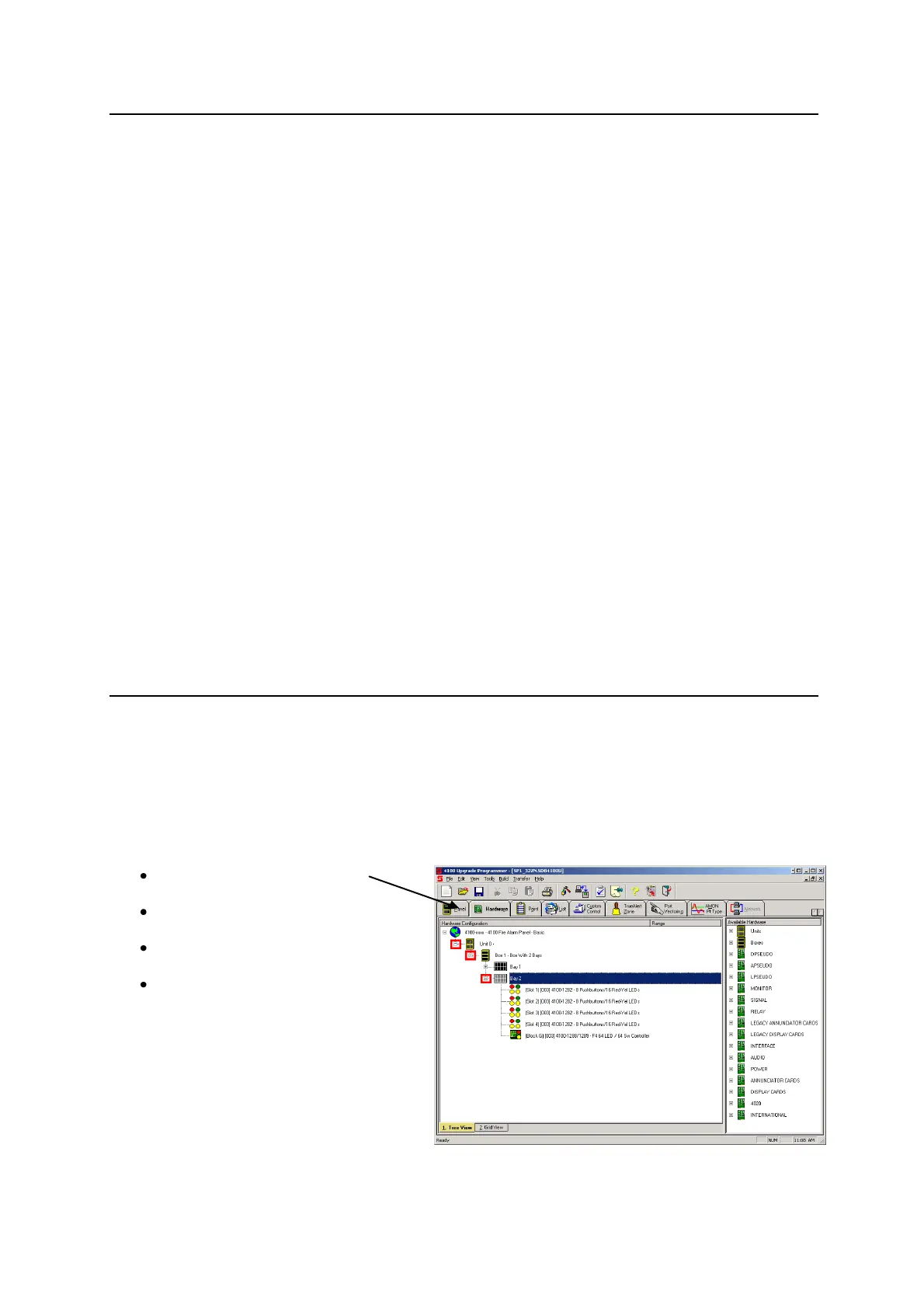
Select the HARDWARE Tab
Click on the “+” sign beside Unit 0.
Click on the “+” sign beside Box 1.
Click on the “+” sign beside Bay 2.