4100U-S1 Programming Guide Document: LT0400
Appendices
Page 12-8 15 December 2010 Issue 1.4
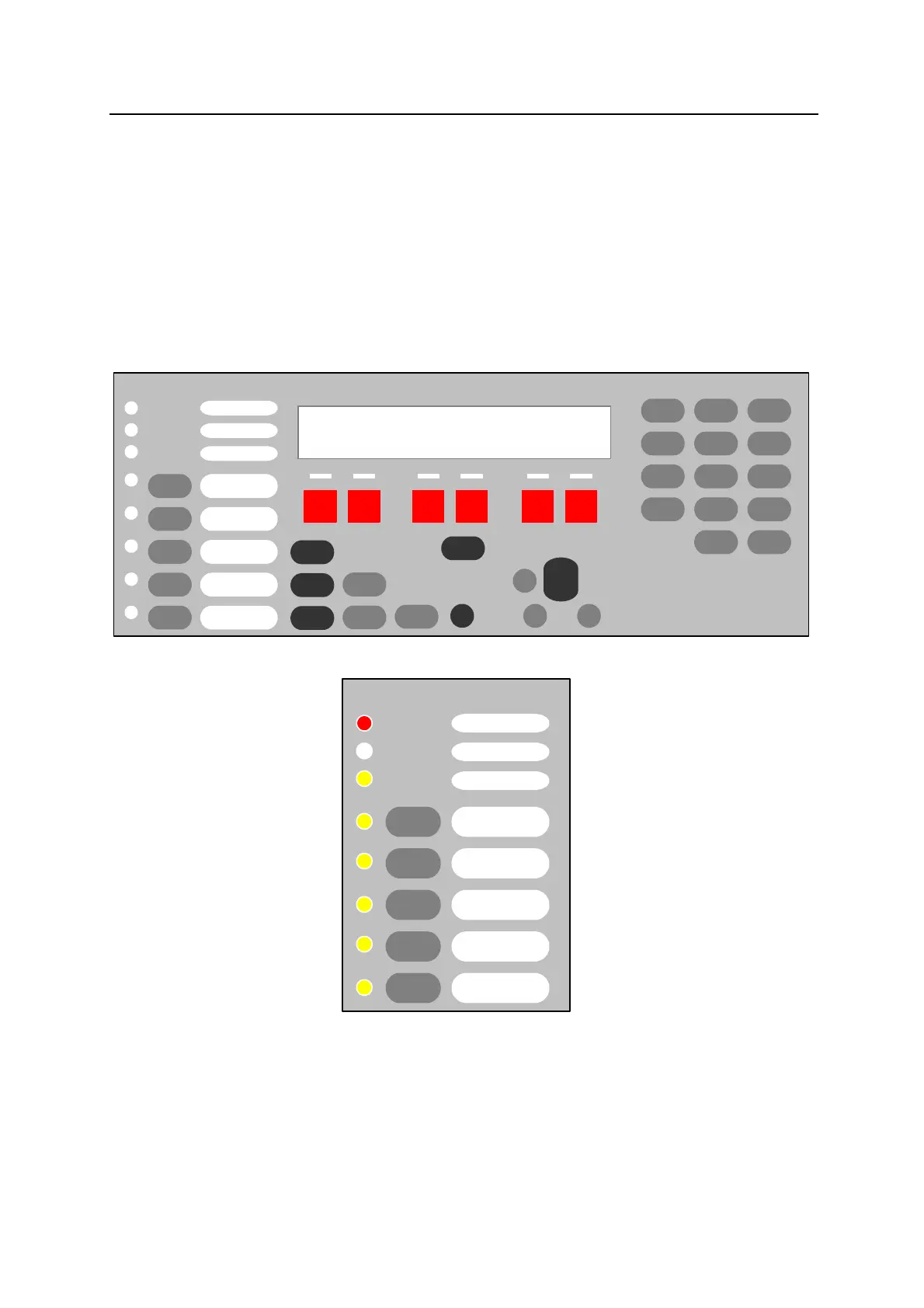
12.3 Appendix C - Custom Control for Control Keys and Indicators
The main part of the Operator Interface (the several ACK keys, numeric keypad and LCD)
has functionality which is controlled directly by the panel software, and cannot be re-
configured.
The Control keys and Indicators at the left end of the Operator Interface provide functionality
which is controlled by Custom Control equations to meet AS 4428.1 requirements.
These equations are part of Program 3. They should not be changed, except under the
direction of Simplex Fire Products, since the operation of the panel may be adversely
affected.
AUX
3
IDNet
6
L
9
DEL
C/Exit
SIG
2
IO
5
A
8
ADDR
0
Enter
ZONE
1
FB
4
P
7
NET
---
2x 40 CHARACTER
LCD DISPLAY
Event
Time
Enable
Disable
On
Arm
Off
Disarm
Auto
WARN SYS
ISOLATE
EXT. BELL
ISOLATE
ACF ISOLATE
ALARM / FAULT
TEST SELECT
FAULT TEST ON
ZONE ALARM
Fire
Alarm
Ack
Pri 2
Ack
Isolate
Ack
Fault
Ack
Alarm
Silence
System
Reset
More
Info
Lamp
Test
Menu
^
Previous
Next
^
V
V
WARN SYS
ISOLATE
EXT. BELL
ISOLATE
ACF ISOLATE
A/C RESET
ALARM / FAULT
TEST SELECT
FAULT TEST ON
ZONE ALARM
0-5-6 Alarm Test Active LED (P514)
0-5-13 Fault Test Active LED (P515)
0-5-8 ACF Isolated LED (P517)
0-5-9 Bells Isolated LED (P518)
0-5-10 Warning Sys Isolated LED
(P519)
0-5-11 Common Alarm LED
0-5-7 A/C Trip LED (P521)
0-5-1 Alarm/Fault/Norm Button (P513)
0-5-2 A/C Reset Button (P522)
0-5-3 ACF Isolate Button (P517)
0-5-4 Bell Isolate Button (P518)
0-5-5 Warning Sys Isolate Button
(P519)