Document: LT0400 4100U-S1 Programming Guide
AS1668 Fan Controls
Issue 1.4 15 December 2010 Page 10-7
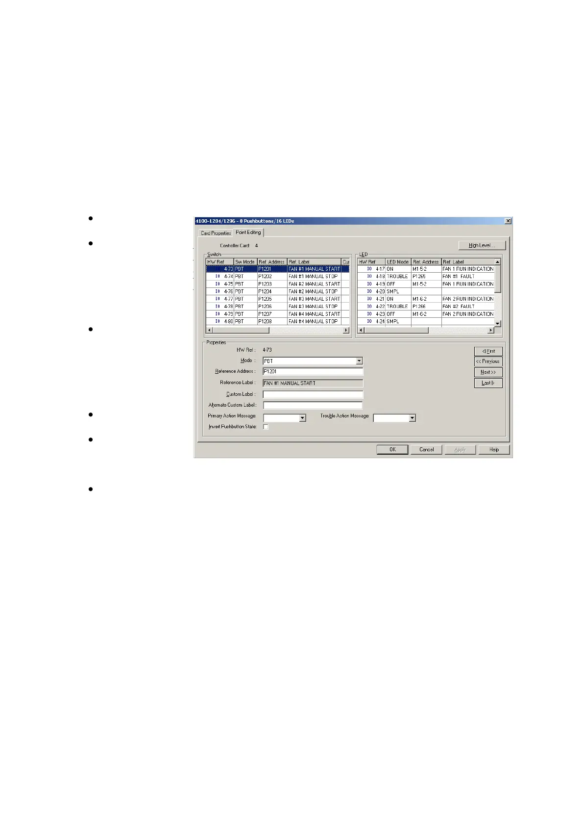
10.4.2 LED Configuration
The LEDs configuration couples the Red Amber and Green LEDs of each fan to a pseudo
point.
Each fan uses 4 LEDs:
LED 1 set = Red LED is ON = Fan is running.
LED 2 set = Amber LED is ON = Fan is faulty.
LED 3 set = Green LED is ON = Fan is not running.
LED 4 is not used.
These pseudo points can be monitored via the panel‟s display screen and referred to from
the online executable via custom controls.
In the Mode text
box enter „ON‟.
In the Reference
Address text
box enter the
address of the
airflow
monitoring
device.
Highlight the next
line to configure
the next entry
with the Fault
pseudo point
(starting at
P1265).
In the Mode text
box enter „OFF‟.
In the Reference
Address text
box enter the
address of the airflow monitoring device.
Every 4
th
line (the 4
th
entry of each fan) should be left as SMPL and without a pseudo
point configured.
When all the configured fans have pseudo points for the Switch and LED – click OK.