7-5
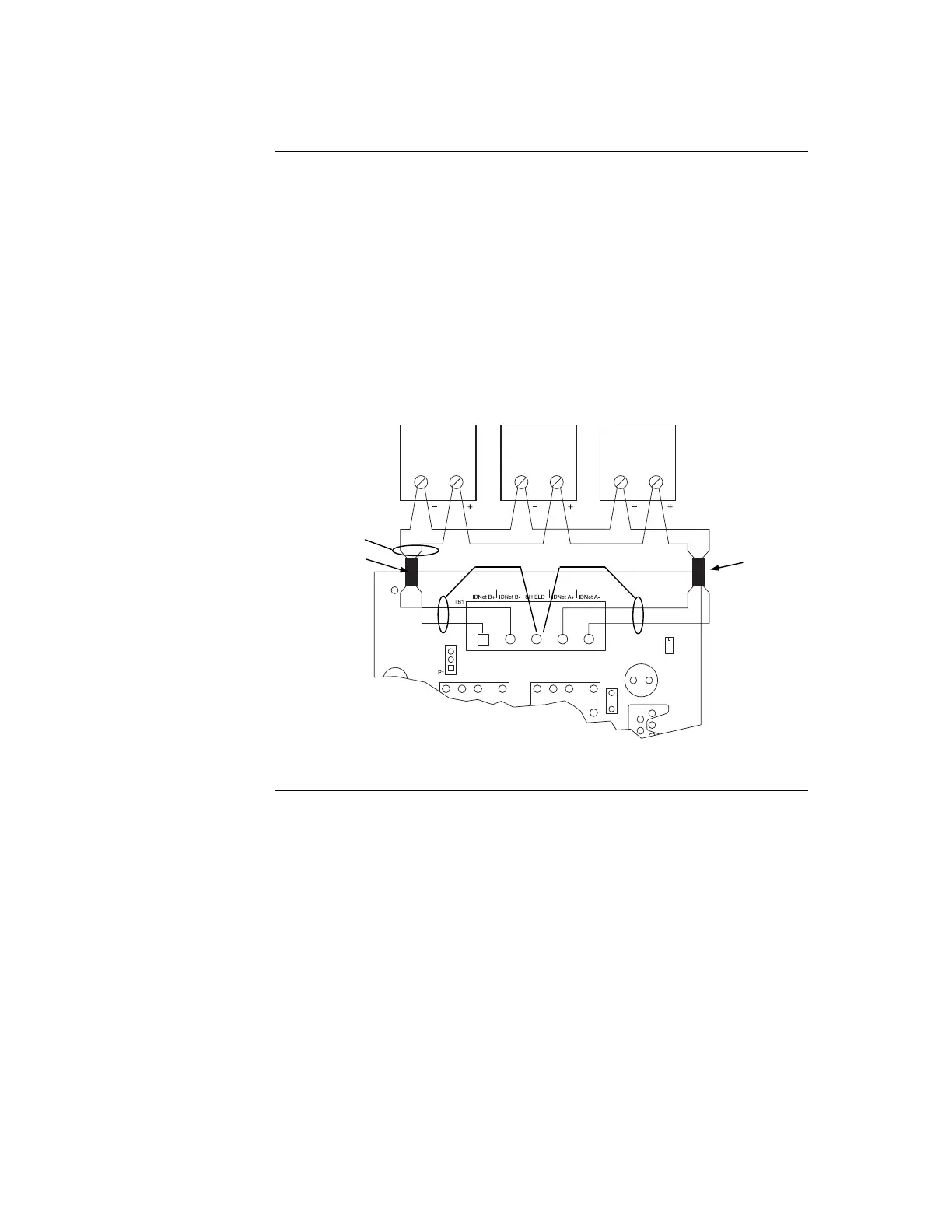
To connect the IDNet card to devices using Class A (loop) wiring, see Figure 7-5 and the
following:
1. Route wire from the IDNet B+, IDNetB- outputs on TB1 of the IDNet card to the
appropriate inputs on a peripheral IDNet device.
2. Route wire from the first IDNet device to the next IDNet device. Repeat for each
device.
3. Route wire from the last IDNet device back to the IDNet A+ and IDNet A-
inputs on the same IDNet port.
4. Separate every 40 devices (at most) with a IDNet communications isolator, e.g.
4090-9116 isolator module or 4098-9793EA isolator base.
5. Separate the power feed to sounder bases or 6 point I/O modules in different
zones using the 4090-9117 Power Isolate module.
+
1
2
1 212
Figure 7-3. Class A (loop) Wiring
Continued on next page
Wiring to IDNet Devices, Continued
Class A Wiring
IDNET CARD
IDNET DEVICES
0.75 mm
2
to 4 mm
2
SHIELD
SHIELD
FERRITE BEAD
FERRITE BEAD
(see Figure 7-1)