2-20
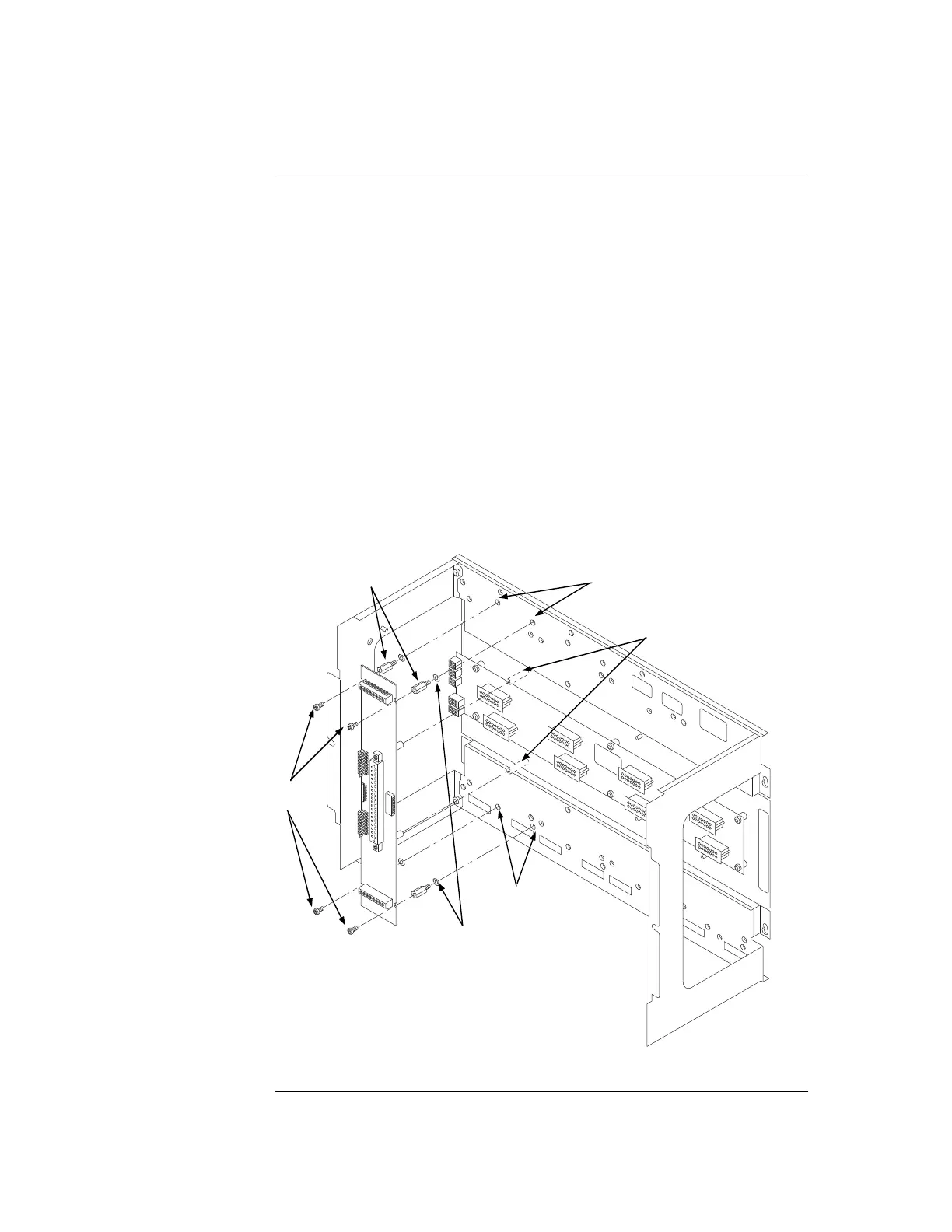
Use the following procedure when installing motherboards in an expansion bay. If
practical, start at the left and fill to the right. The pins of the left connector (P1) on the
leftmost motherboard must be removed. The motherboard mounting items are available as
4100-KT0468.
1. Orient the motherboard with connector J1 on the right and header P1 on the left.
2. Attach the four metal threaded standoffs and lockwashers into the screw holes on the
chassis.
3. Attach two grey plastic standoffs to the motherboard socket mounting screws.
4. Secure the motherboard to the standoffs using four #6 Torx screws as shown below.
WARNING: If the expansion bays are mounted to the front of the cabinet (earlier style),
a 4100 Motherboard with daughter card cannot be fitted directly behind a
64/64 LED/Switch Controller. The same applies to modules mounted on
the bay mounting bracket (FA2255), e.g. ME0426 T-GEN.
With the newer rear-mounted expansion bays, this restriction does not
apply.
Figure 2-14. Installing the Motherboard in a 4100ES Expansion Bay
Step 5. Installing Modules into Expansion Bays (4100ES), Continued{xe
"mounting: motherboards to 4100U back boxes"}
Installing
Motherboards
#6 SCREWS
LOCKWASHERS
METAL
STANDOFFS
SCREW HOLES
SCREW HOLES
PLASTIC STANDOFFS