2-21
The LED/switch user interface consists of a variety of modules, which are configured via
the ES Programmer. Each display module contains between 8 and 24 switches and LEDs,
each one separately configurable.
User interface functionality is driven by the 64/64 LED/Switch Controller Card, which
mounts behind two of the display modules (typically in positions 1 and 2). The range of
available modules is listed in Appendix K.
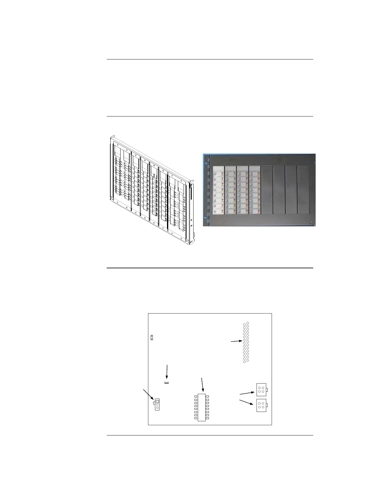
Figure 2-15 shows the two mounting versions of a LED/switch bay.
Earlier style fold-down door Newer style 7U hinged door
Figure 2-15. LED/Switch Modules
The LED/switch controller card mounts behind two LED/switch modules. The
LED/switch controller handles up to 64 switches and 64 LEDs on the modules and
communicates their status to the 4100ES CPU. When a button is pressed on a module, the
controller acknowledges the signal and reacts according to how that switch was
configured via the ES Programmer.
GND1
LED1
P2
12
SW1
1
2
3
4
5
6
7
8
P1
COMM
LOSS
P3
12
Figure 2-16. LED/Switch Controller
Continued on next page
Step 6. Installing LED/Switch Modules into Expansion Bays (4100ES)
Overview
The LED/Switch
User Interface
LED/Switch
Controller Card
LED/SWITCH DISPLAY
CONNECTOR
(P4; reverse side)
POWER/COMMS
CONNECTORS
(P2)
(P3)
COMM LOSS LED (LED1)
ADDRESS DIP
SWITCH (SW1)
REMOTE
ANNUNCIATOR
JUMPER (P1)