7 - 42
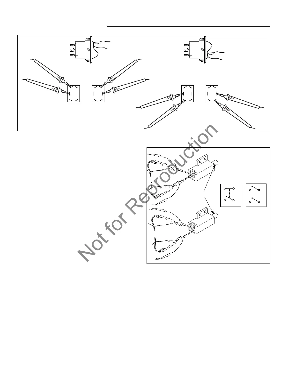
Figure 47. Testing Cut Height Switch
M. Brake Pedal Switch Tests
The foot pedal switch has four terminals for the two con-
tacts. Air-cooled engine models use a N.C. and a N.O.
contact as shown in A of Figure 48. Liquid-cooled engine
models use two N.O. contacts as shown in B of Figure
48.
A N.O. contact is normally open, meaning that when the
brake pedal is at rest (up, not depressed) the switch is
open and will not conduct current. Depressing the brake
pedal (or switch plunger) closes the switch. The opposite
applies for the N.C. contact.
SWITCH TESTS
NOTE: It may be easier to test the switch if the switch is
removed. See Component Location and Replacement for
switch removal procedures, earlier in this section.
Figure 48. Brake Pedal Switch
Plunger
7 Electrical System Service
Component Tests
L. Height of Cut Switch Test
See Figure 47.
1. If necessary, remove the steering wheel and dash-
board. (See Section 8, POWER STEERING SYS-
TEM SERVICE.)
2. Remove the connector from the height of cut switch.
3. Remove the height of cut switch from the control
panel.
4. Set VOM to Ohm.
5. Press the switch to the up position and check the ter-
minals on the back of the switch as shown in
Figure 47. There should be continuity on the termi-
nals shown when the switch is pressed.
6. Press the switch to the down position and check the
terminals on the back of the switch as shown in
Figure 47. There should be continuity on the termi-
nals shown when the switch is pressed.
1. Pull the wire harness off the back of the switch.
2. Set VOM to Ohm. With the brake pedal up (plunger
not depressed) probe the switch terminals (see
Figure 48). The VOM should show no continuity for
N.O. contacts and continuity for N.C. contacts.
3. Depress the brake pedal and engage the parking
brake.
4. With the brake pedal depressed (plunger depressed)
Probe the switch terminals (see Figure 48). The VOM
should show continuity for N.C. contacts and no con-
tinuity for N.O. contacts.
5. Replace a switch that does not pass all tests.