12 - 7
12 Brake System Service
Brake Pedal Assembly Replacement
Brake Pedal Assembly Replacement
1. Park the tractor on a level surface.
2. Place blocks in front of and behind the front wheels.
3. Turn the ignition key switch to the OFF position,
remove the key, set the parking brake, and turn the
PTO switch off.
4. Disconnect the negative (-) battery cable
(see Section 7, ELECTRICAL SYSTEM SERVICE).
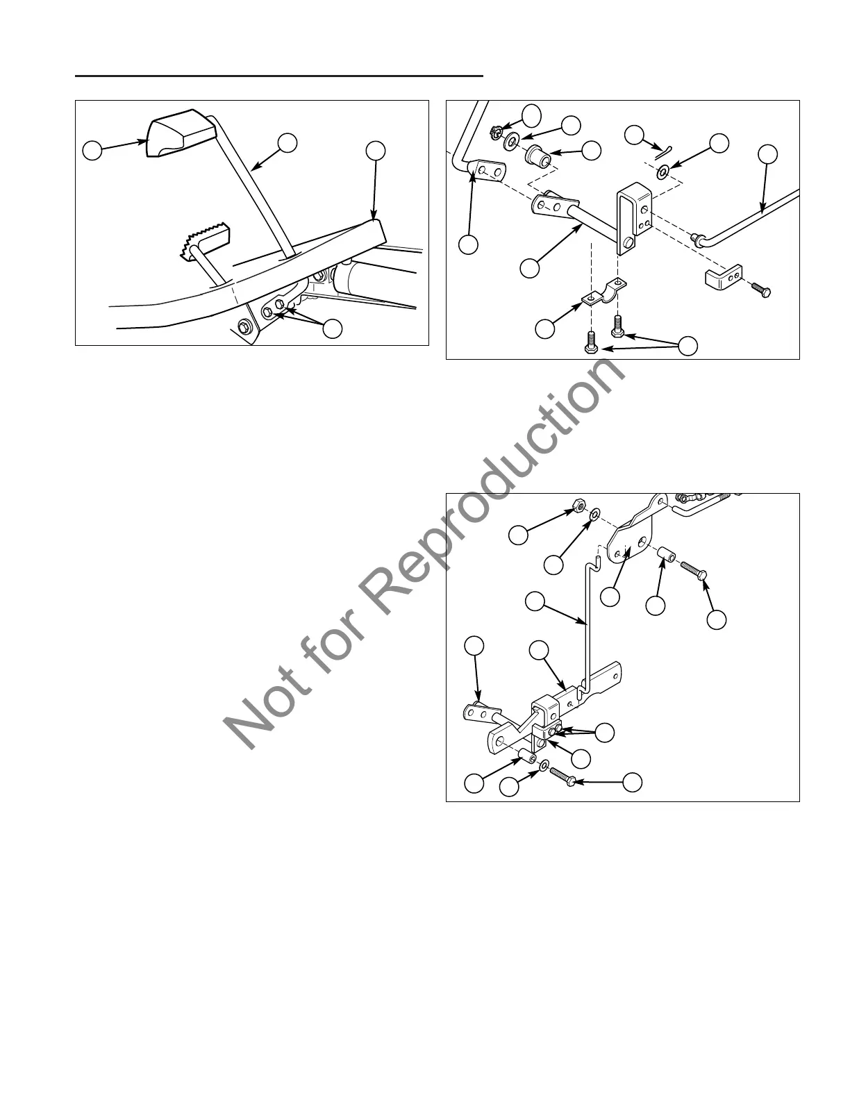
5. Remove the two taptite screws (D, Figure 7) attach-
ing the brake pedal arm (B) to the brake control arm.
Remove the brake pedal arm (B) from the foot rest.
6. Remove the cotter pin (E, Figure 8) and washer (F)
from the brake control rod (G). Remove the brake
control rod from the brake control arm (J).
7. Remove the capscrews (H) that are securing the
strap (I) and brake control arm (J).
8. Remove the two capscrews (I, Figure 9) that are
securing the actuator tab (J) and remove the actuator
tab.
9. Remove the capscrew (K), washer (L), and spacer
(M) from the parking brake bracket (B).
10. Remove the parking brake bracket (B) from the park-
ing brake rod (C) and then remove the parking brake
rod from the pivot bracket (F).
11. Remove the klip ring (B, Figure 8) and washer (C)
from the end of the brake control arm (J). Slide the
control arm out from the frame and bushing (D).
12. Assemble in reverse order.
13. Perform brake pedal switch adjustment (see Section
4, ADJUSTMENTS).
Figure 8. Removing Brake Pedal Control Arm
A. Brake Pedal Arm F. Washer
B. Klip Ring G. Brake Control Rod
C. Washer H. Capscrews
D. Bushing I. Strap
E. Cotter Pin J. Brake Control Arm
A
J
I
G
F
E
D
C
B
B
A
Figure 7. Brake and Speed Pedal Arms
A. Brake Pedal Pad C. Foot Rest
B. Brake Pedal Arm D. Taptite Screws
D
C
H
J
Figure 9. Parking Brake Linkage
A. Brake Control Arm H. Capscrew
B. Parking Brake Bracket I. Capscrews
C. Parking Brake Rod J. Actuator Tab
D. Lock Washer K. Capscrew
E. Hex Nut L. Washer
F. Pivot Bracket M. Spacer
G. Spacer
K
B
A
M
L
F
H
G
D
E
C
I