9 Drive Control Service
Cruise Control Service
9 - 10
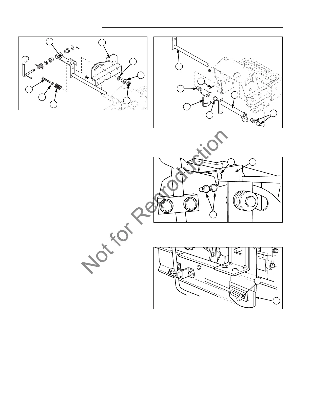
Figure 9. Remove Control Lever
A. Cruise Control Handle D. Roll Pin
B. Bushing E. Brake Cross Shaft
C. Cruise Control Arm
C
D
A
E
B
B
B
10. Remove the hex nut (H, Figure 8), spacer (G), and
washer (F) that is holding the bolt (B), washer (C),
and spring (D) to the cruise control handle (A) and
slotted bracket (E).
11. Remove roll pin (D, Figure 9) from cruise control arm
(C) and cruise control handle (A).
12. Remove cruise control handle (A) by sliding out of the
cruise control arm (C) and brake cross shaft (E).
13. Remove cruise control arm (C), brake cross shaft (E)
and bushings (B).
14. Inspect bushings (B) for wear or cracks, replace if
necessary.
Assemble in reverse order of disassembly and adjust the
cruise control switch with the following steps.
Note: Verify that the cruise control tension is assembled
properly and the tension is properly set before perform-
ing this adjustment.
The cruise control switch (A, Figure 10) is actuated, the
plunger (B) being pressed inward towards the switch
body, when the cruise control lever (C) is in the disen-
gaged position. This opens the contacts inside the
switch, which will extinguish the cruise control indicator
lamp in the instrument panel.
1. Verify that the cruise control lever is fully disengaged.
Loosen the two capscrews (D, Figure 10) and posi-
tion the switch so that the plunger (B) of the cruise
control switch (A) is fully actuated by being pressed
against the control lever (C).
2. Once the cruise control switch (A) is positioned, tight-
en the capscrews (D).
3. Turn the ignition key switch to the "ON" position, the
cruise control instrument panel lamp should be off. If
not, re-adjust.
Figure 8. Cruise Control Tension Hardware
A. Cruise Control Handle E. Slotted Bracket
B. Bolt F. Washer
C. Washer G. Spacer
D. Spring H. Hex Nut
B
F
A
E
C
D
G
H
Figure 10. Cruise Control Switch Adjustment
A. Cruise Control Switch C. Cruise Control Lever
B. Plunger D. Capscrews
Figure 11. Cruise Control Point of Engagement
A. Control Lever Assembly B. Cruise Control Rod
A
CB
D
A
B
4. Verify that the cruise control indicator lamp is not illu-
minated when the end of the cruise control rod
(B, Figure 11) is not engaging the pin on the control
lever assembly (A). Adjust switch as necessary to
find a medium.