8 - 11
8 Power Steering Service
Front Axle Removal and Installation
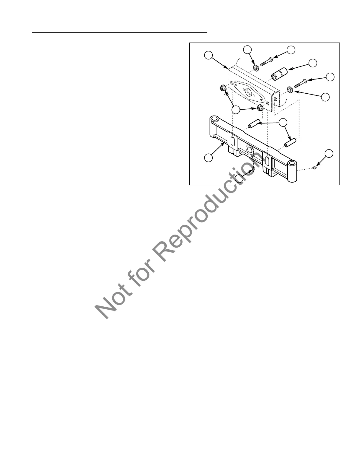
Figure 14. Front Axle Removal
A. Frame E. Axle Tube Spacers
B. Washer F. Flange Nut
C. Capscrew G. Grease Fitting
D. Axle Pivot Spacer H. Axle
Front Axle Removal and Installation
1. Park the tractor on a level surface.
2. Place blocks in front of and behind the rear wheels.
3. Turn the ignition key switch to the OFF position,
remove the key, set the parking brake, and turn the
PTO switch off.
4. Disconnect the negative (-) battery cable
(see Section 7, ELECTRICAL SYSTEM SERVICE).
5. Disconnect spark plug wires to prevent the possibility
of accidental starting.
6. Remove the PTO belts (see Section 16, PTO
CLUTCH SERVICE).
NOTE: The axle cannot be removed without removing
the PTO belts and drive because the PTO drive shaft
goes through the axle and frame.
7. Remove the PTO drive (see Section 16, PTO
CLUTCH SERVICE).
8. Hoist the front end of tractor and securely support the
front end using the proper jack stands under the
frame so that work can be safely performed under-
neath the tractor.
9. Remove both front wheels (see Section 3, MAINTE-
NANCE).
10. Disconnect front axle steering cylinder (see Steering
Cylinder Removal, in this section).
11. Remove front spindles (see Front Spindles Removal,
in this section).
12. Support the axle and remove the capscrews (C,
Figure 14), washers (B), and flange nuts (F) that are
holding the axle (H) in the frame (A).
13 Remove the axle pivot spacer (D) and axle tube
spacers (E) then lower the axle down out of the
frame.
14. Reassemble in reverse order. Torque flange nuts (F)
to 75 ft.lbs. Lube axle pivot spacer (D) with grease.
C
B
C
B
A
D
E
H
G
G
F