19 Implement Lift Service
Lift Shaft and Cylinder Replacement
19 - 8
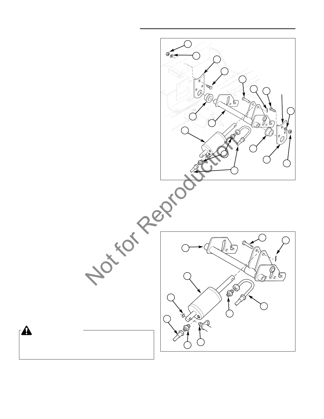
Figure 7. Lift Cylinder Replacement
A. Lift Shaft Assembly E. Hydraulic Hoses
B. Clevis Pin F. Pivot Shaft
C. Cotter Pin G. Klip Ring
D. Hydraulic Fittings H. Lift Cylinder
A
Figure 6. Lift Shaft Assembly Replacement
A. Hex Nut G. Clevis Pin
B. Lock Washer H. Cotter Pin
C. Bearing Plate I. Hydraulic Hoses
D. Capscrew J. Hydraulic Fittings
E. Bushing K. Lift Cylinder
F. Lift Shaft Assembly
A
Lift Shaft Assembly Replacement
1. Park the tractor on a level surface.
2. Turn the ignition key switch to the OFF position,
remove the key, set the parking brake, and turn the
PTO switch off.
3. Disconnect the negative (-) battery cable
(see Section 7, ELECTRICAL SYSTEM SERVICE).
4. Remove the mower deck and any other accessories
(see Section 6, COMMON SERVICE PROCEDURES.)
5. Disconnect spark plug wires or glow plug wires to
prevent the possibility of accidental starting while the
PTO is being adjusted.
6. From underneath the unit, remove the cotter pin (H,
Figure 6) from the clevis pin (G) that is securing the
lift cylinder (K) to the lift shaft assembly (F). Slide cle-
vis pin out.
7. Remove the three capscrews (D), lockwashers (B),
and nuts (A) that are securing the right lift shaft
assembly (F) and bearing plate (C) to the frame.
8. Slide the lift shaft assembly (F) and bushings (E)
down and out from the frame.
9. Remove the bushings (E) from the lift shaft assembly
(F) to inspect the bushings for cracks or excessive
wear. Replace bushings if necessary.
10. Assemble in reverse order.
Lift Cylinder Replacement
1. Park the tractor on a level surface.
2. Turn the ignition key switch to the OFF position,
remove the key, set the parking brake, and turn the
PTO switch off.
3. Disconnect the negative (-) battery cable
(see Section 7, ELECTRICAL SYSTEM SERVICE).
4. Remove the mower deck and any other accessories
(see Section 6, COMMON SERVICE PROCEDURES.)
5. Disconnect spark plug wires or glow plug wires to
prevent the possibility of accidental starting while the
PTO is being adjusted.
WARNING
Be aware that the hydraulic fluid is under pres-
sure. Use caution when disconnecting hydraulic
lines.
B
C
D
E
F
E
C
G
K
H
D
A
B
J
I
H
G
E
B
C
E
D
F
D
Welded
to frame