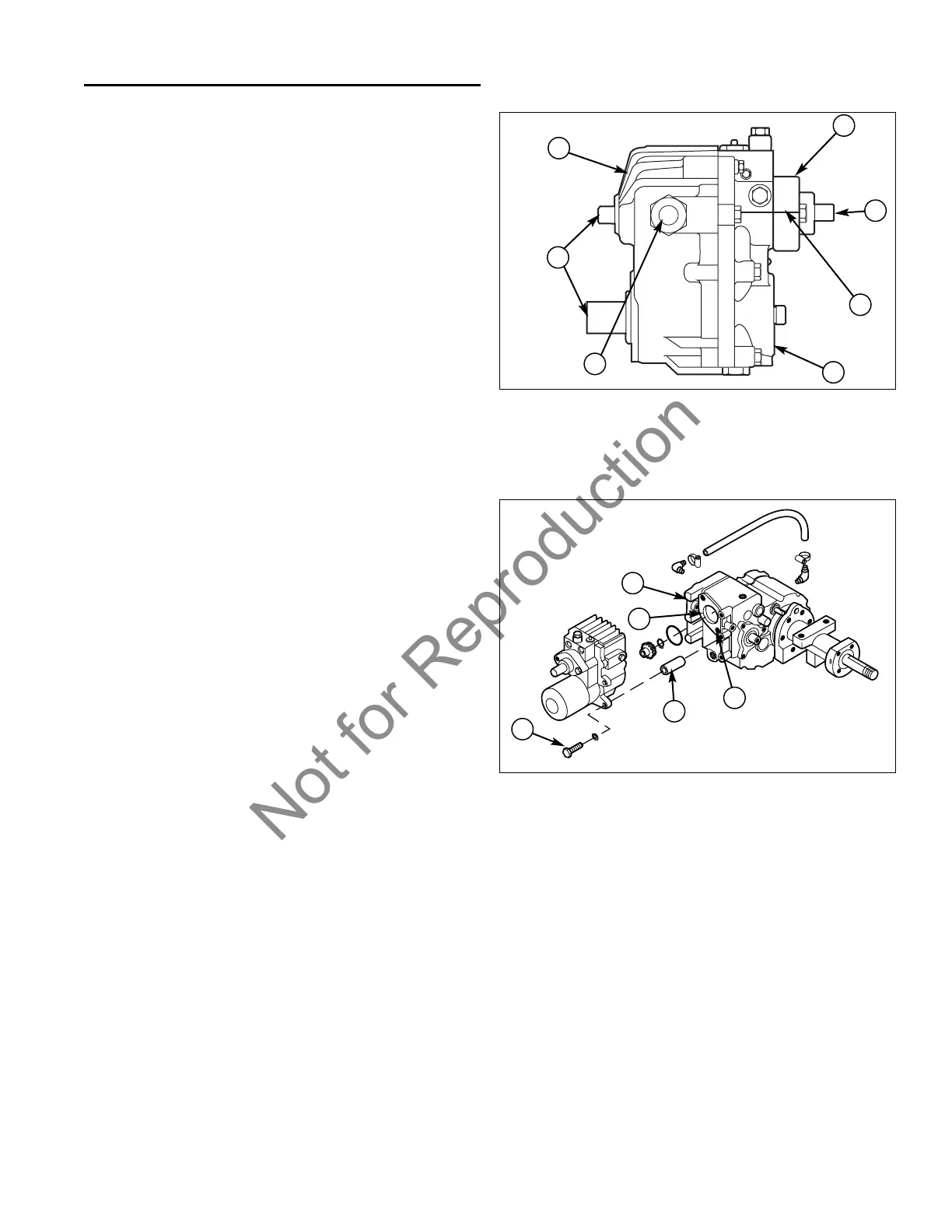
Figure 11. U-Type Main Sections
A. Housing E. Input Shaft
B. End Section F. Output Shafts
C. Charge Pump Housing G. Control Shaft
D. Scribe Location
E
C
D
B
A
10 - 9
10 U-Type Hydrostatic Unit Service
Separating/Assembling Pump & Transaxle
SEPARATING PUMP & TRANSAXLE
General
Cleanliness is the primary means of ensuring satisfactory
transmission life. Do not allow ANY particulate (such as
dirt or sand) or chemical contaminant's, even water, to
enter the Hydrostatic Unit during removal, repair, or
installation.
Always thoroughly clean the Hydrostatic Unit before any
hoses are disconnected.
IMPORTANT NOTE: Do not use paint thinner, acetone,
or acetone-based solvents. These may damage O-rings,
gaskets, or seals.
Check especially that the areas around hose fittings,
valves, and external shafts are clean and free of dirt and
grease.
Do not pound or hammer on input (E, Figure 11), output
(F), or control shafts (G) when installing control linkage
or drive coupling. Hammering on these shafts WILL dam-
age the Hydrostatic Unit.
Always use new hydraulic fluid and filter.
1. Remove the transaxle and pump from the tractor (see
Section 11, TRANSAXLE REMOVAL AND INSTAL-
LATION).
2. Separate the pump and transaxle by removing the
capscrews (D, Figure 12) and spacers (E), then gen-
tly separating the pump from the transaxle.
C
B
ASSEMBLING PUMP & TRANSAXLE
1. Clean the common mounting surfaces on the
Hydrostatic Unit and transaxle case (A, Figure 12),
removing all traces of old gasket material. Remove
any gasket material found in each of two cavities (B)
on the transfer case.
2. Assemble the pump to the transaxle in reverse order
of separation.
3. Install the pump and transaxle (see Section 11,
TRANSAXLE REMOVAL AND INSTALLATION).
4. Adjust all tractor drive controls (refer to Section 4,
ADJUSTMENTS).
Figure 12. Hydrostatic Unit Installation
A. Transfer Case Housing D. Capscrews
B. Cavity E. Spacers
C. Gasket Eliminator Application
B
A
C
HYDROSTATIC UNIT DISASSEMBLY,
REPAIR, AND REASSEMBLY
General
Clean the Hydrostatic Unit before disassembly.
REMEMBER: CLEANLINESS IS THE PRIMARY
MEANS OF ENSURING SATISFACTORY TRANSMIS-
SION LIFE.
IMPORTANT NOTE: Do not use paint thinner, acetone,
or acetone-based solvents. These may damage O-rings,
gaskets, or seals.
The U-Type Hydrostatic Transmission consists of two
main sections, the housing section (A, Figure 12) and the
center section (B).
D
E