14 Hood, Dash, & Foot Rest Service
Remove and Replace
14 - 8
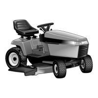
Bumper Replacement
1. Remove the hood from the tractor (see Hood
Removal in this section).
2. Remove capscrews (B, Figure 8), lockwashers (D),
and nuts (E) that are securing the bumper (A) to the
frame (C).
3. Repair or replace the appropriate part and assemble
in reverse order.
4. Replace the hood on the tractor (see Hood
Replacement, in this section).
Figure 8. Remove and Replace Bumper
A. Bumper D. Lockwasher
B. Capscrew E. Nut
C. Frame
B
E
D
A
C
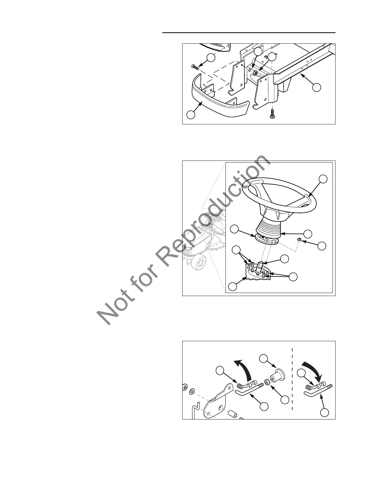
Dashboard Removal
1. Turn the ignition key switch to the OFF position,
remove the key, set the parking brake, and turn the
PTO off.
2. Disconnect the negative (-) battery cable (see
Section 7, ELECTRICAL SYSTEM SERVICE).
3. Peel up the rubber boot (B, Figure 9) covering the tilt
assembly (G).
4. Remove the four flange nuts (C) securing the tilt
assembly base (G) and lift off of the tower assembly.
GAS MODELS
5. Mark and disconnect the throttle and choke control
cables from the engine. (Refer to engine manufactur-
er’s manual.)
6. Locate the rod (A, Figure 10) extending from the back
of the parking brake knob (D). Rotate the connector
clip (B) off the rod and disconnect the linkage.
DIESEL MODELS
7. Mark and disconnect the throttle control cable from
the engine. (Refer to engine manufacturer’s manual.)
8. Remove the knob (D, Figure 10) and nut (C) from the
parking brake rod (A).
ALL MODELS
9. Lift the dashboard and disconnect the wire harnesses
from the following electrical components (see Figure
11):
A. Ignition Switch
B. PTO Switch
C. Headlight Switch
D. Dashboard Display
E. Mower Cutting Height Switch
Note the small dot on the cutting height switch connector
plug. When reconnecting the plug, the dot should face
the same direction (to the right).
Figure 9. Steering Wheel Tilt Assembly Removal
A. Steering Wheel E. Mounting Screws
B. Rubber Boot F. Dashboard
C. Nut G. Tilt Assembly Base
D. Steering Pump Shaft
B
G
A
C
D
F
E
E