11 Transaxle Removal & Installation
Transaxle Installation – All Models
11 - 8
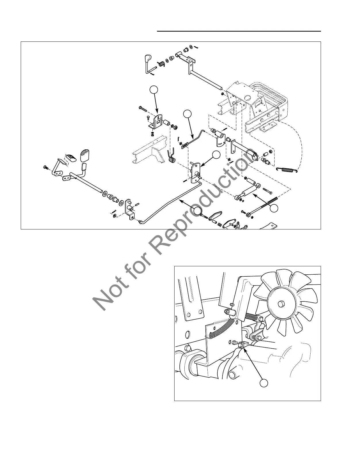
13. Install the shock absorber (E, Figure 13) to the frame
and control lever assembly (C) on the right side of the
hydrostatic housing, and secure with the original
hardware.
14. Install the pedal stop plate assembly (D) on the top of
the right frame member, and secure with the original
hardware.
15. Install the cruise to lever assembly control rod (B)
and the pedal to lever direction control rod (A) to the
control lever assembly (C) on the right side of the
hydrostatic housing, and secure with the original
hardware.
16. Install the differential lock cable clevis (A, Figure 14)
to the control rod on the left side of the transaxle with
the original hardware.
Figure 14. Differential Lock Cable Installation
A. Cable Clevis
A
Figure 13. Linkage Installation
A. Pedal Direction Control Rod C. Control Lever Assembly E. Shock Absorber
B. Cruise Assembly Control Rod D. Pedal Stop Plate Assembly
A
D
B
C
E