13 - 33
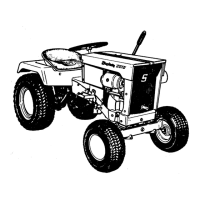
5. Install the guard (E, Figure 41), stub shaft (D), PTO
clutch assembly (C), and PTO belt set (B) to the
engine, using the original hardware (refer to Section 16,
PTO CLUTCH SERVICE, if additional information is
required).
6. Plug the PTO clutch (A) connector into the main har-
ness connector.
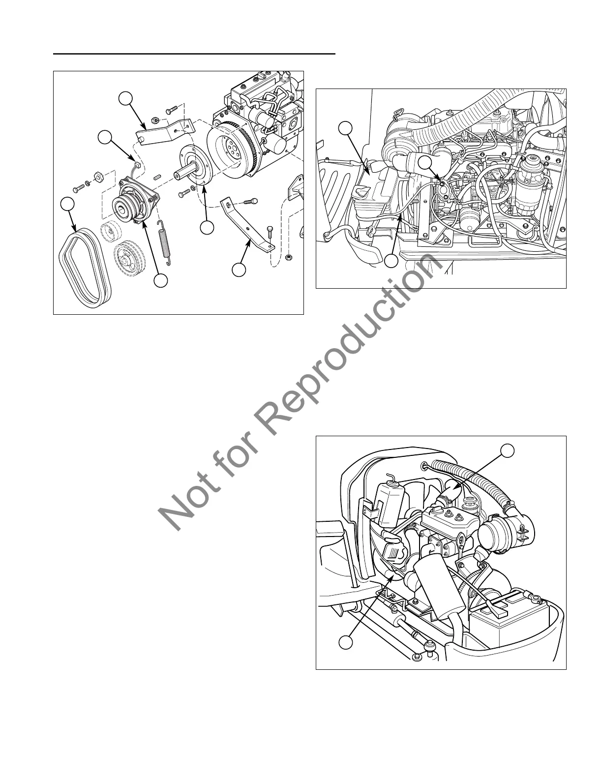
7. Install the upper radiator hose (A, Figure 43) to the
engine and radiator, and tighten both hoses clamps
securely.
8. Install the lower radiator hose (B) to the engine and
radiator, and tighten both hoses clamps securely.
9. Connect the negative battery cable (C, Figure 42) to
the left front of the engine block (B).
13 Engine Removal & Installation
Briggs & Stratton - Engine Installation
Figure 43. Engine Component Installation – Front
A. Radiator Hose (Upper)
B. Radiator Hose (Lower)
A
B
Figure 41. PTO Clutch Removal
A. Electrical Connector D. Stub Shaft
B. Belt Set E. Guard
C. PTO Clutch Assembly F. Clutch Stop Bracket
C
D
F
A
B
E
Figure 42. Engine Component Removal – Front
A. Battery
B. Engine Block Ground Location
C. Negative Battery Cable
A
C
B