15 - 7
Figure 6. Lower Seat Deck Mounting Hardware
A. Foot Rest D. Capscrew (Flange)
B. Frame E. Capscrew
C. Seat Deck F. Nut
15 Seat Deck & Fuel Tank Service
Seat Deck Removal and Installation
A
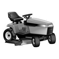
Figure 5. Tractor Belly View
A. Lower Mounting Hardware
A
A
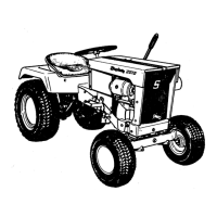
Figure 7. Remove Tail Light Sockets and Bulbs
A. Tail Light Bezel C. Bulb
B. Socket D. Seat Deck
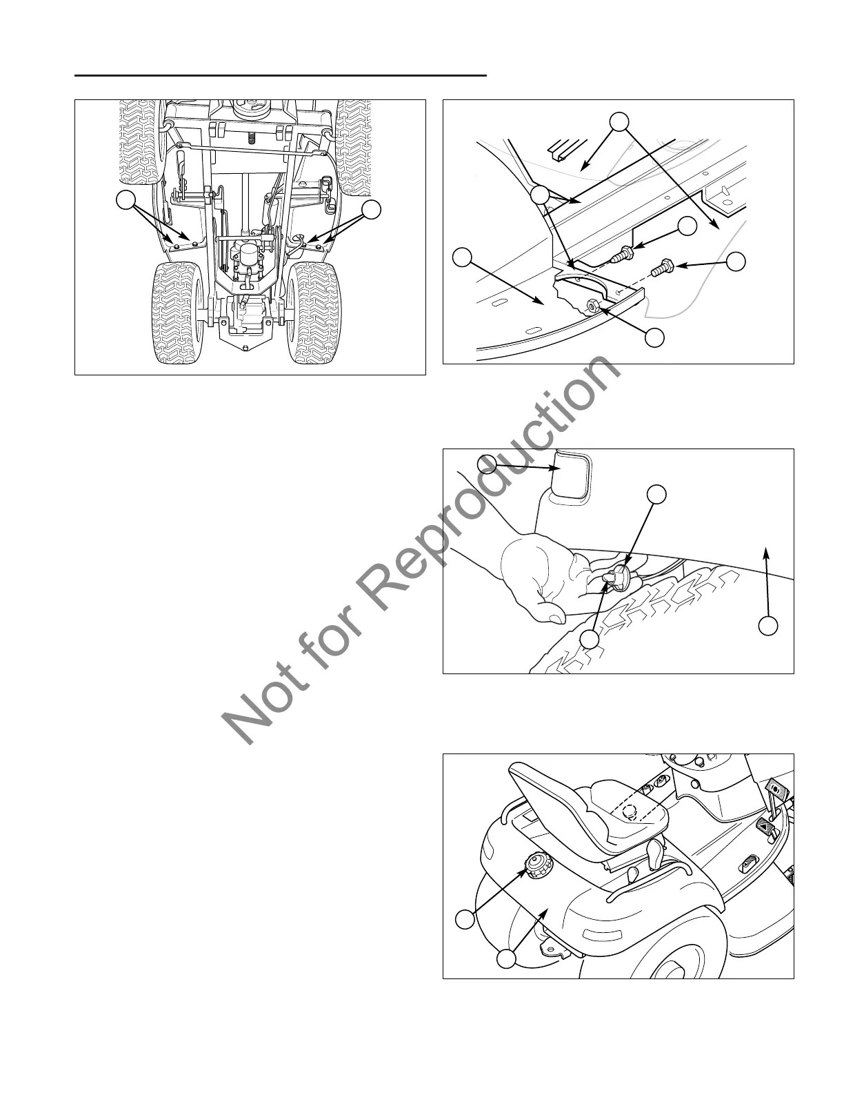
Figure 8. Remove Seat Deck and Tunnel
A. Gas Cap B. Seat Deck
A
B
D
F
E
D
B
C
B
C
A
4. Secure the seat deck lower mounting hardware
(A, Figure 5) consisting of two hex flange capscrews
(D, Figure 6) and two nuts (F) with two hex head cap-
screws (E) securing the seat deck to the foot rests
(A). DO NOT tighten the hardware at this time.
NOTE: Some models have the hex head capscrew and
hex nut on the inner mounting holes and the hex flange
capscrew on the outer holes. Make sure the hex flange
capscrew is placed only in the threaded hole, regardless
of whether it is the inner or outer hole.
5. Secure the seat deck upper mounting hardware con-
sisting of two capscrews (E, Figure 4) securing the
seat deck to the seat deck support (H, Figure 3). DO
NOT tighten the hardware at this time.
6. Reassemble the cruise control lever as shown in
Figure 3.
7. Tighten the lower and upper seat deck mounting
hardware.
8. Press the two-speed control knob back onto the two-
speed control lever.
9. Reconnect the seat switch harness (F, Figure 4) and
plug (B) to the seat switch (D).
10. Reinstall the tail light sockets (B, Figure 7) and bulbs
(C) into the tail light bezel (A).
11. Reconnect the negative battery cable.