16 - 7
16 PTO Clutch Service
Clutch Removal
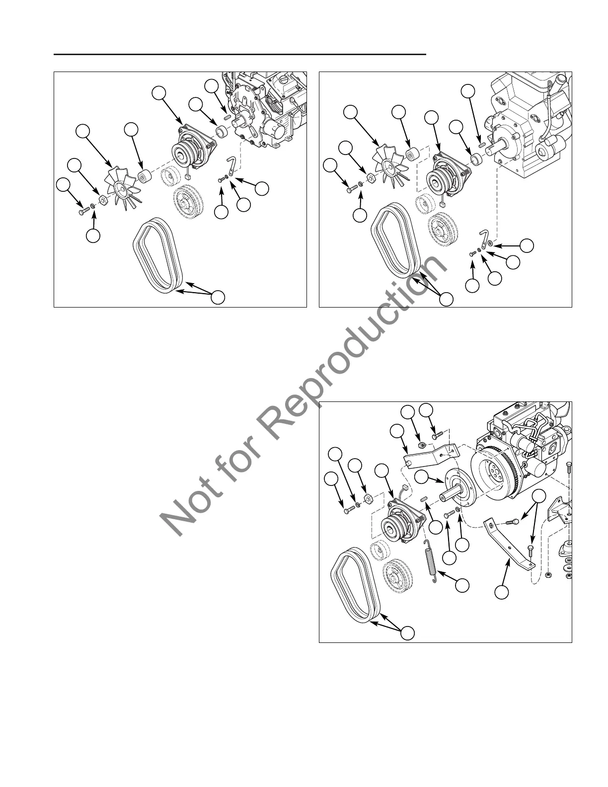
Figure 6. PTO Clutch (Kohler Models)
A. Crankshaft Bolt G. Fan
B. Lockwasher H. Fan Spacer
C. Hex Washer I. Clutch Spacer
D. PTO Clutch J. Capscrew
E. Belts K. Anti-Rotation Rod
F. Key
Figure 7. PTO Clutch (Kawasaki Models)
A. Crankshaft Bolt G. Fan
B. Lockwasher H. Fan Spacer
C. Hex Washer I. Clutch Spacer
D. PTO Clutch J. Capscrew
E. Belts K. Anti-Rotation Rod
F. Key L. Washer
L
Figure 8. PTO Clutch (B&S Diesel Models)
A. Crankshaft Bolt G. Clutch Spring
B. Lockwasher H. Clutch Stop Bracket
C. Hex Washer I. Nut
D. PTO Clutch J. Capscrew
E. Belts K. Stub Shaft
F. Key L. Support Bracket
G
10. Remove the PTO clutch (D, Figure 6 and 7) and
spacer (I).
NOTE: Be aware of the key on the crankshaft so that it
does not fall to the ground or become lost.
11. If the anti-rotation rod (K, Figure 6 and 7) is being
replaced or the engine is being removed, remove the
anti-rotation rod (K) by removing the capscrew (J)
and lockwasher (B).
DIESEL ENGINE MODELS
12. Use a spring puller or a small rope loop to release the
clutch spring (G, Figure 8).
13. Remove the PTO clutch (D).
NOTE: Be aware of the key on the crankshaft so that it
does not fall to the ground or become lost.
14. If the stub shaft (K) is being replaced or the engine is
being removed, remove the stub shaft
(K) by removing the capscrews (J) and lockwashers
(B).
15. Remove the clutch stop bracket (H) by removing the
nut (I) and capscrew (J) that are securing the clutch
stop bracket to the support bracket (L) and remove
the capscrew (J) securing the clutch stop bracket to
the engine.
K
B
J
E
B
A
C
G H
D
I
F
A
B
C
G
H
D
I
F
E
K
B
J
E
L
J
A
B
C
D
H
I
J
B
J
F
K