© Feb. 2023 24 TB20J Plus Operation Manual
PRE-OPERATION INSPECTION
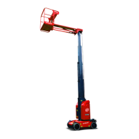
Table 5-1
1. Platform
7. Base boom 13. Engine
2. Foot switch
8. Cable track
14. Fuel tank
3. Platform controller 9. Front wheel (steering wheel) 15. Hydraulic tank
4. Jib boom (if equipped) 10. Ground controller
16. Lashing point
5. Second telescopic boom
11. Main power switch
6. First telescopic boom 12. Rear wheel (non-steering wheel)
5.2 MACHINE POSITIONS
The machine can be set in stowed, transport, operating
and non-operating positions. Each position is described
in detail below:
• Stowed position: The boom tube is fully retracted
and lowered.
• Transport position: The boom tube is horizontal
and fully retracted, and the jib boom is fully lowered.
• Operating position: The main boom is elevated to
more than 15° above horizontal, or the boom tube
extends more than 1.2m (3.9ft).
• Non-operating position: The main boom is ele-
vated to no more than 15° above horizontal, or the
boom tube extends no more than 1.2m (3.9ft).
5.3 PRE-START INSPECTION
If the machine is found to be damaged, not
working properly, or has any unauthorized
changes that differ from the conditions before
delivery, the machine should be stopped and
marked immediately. Report the fault to the
relevant maintenance personnel and do not
operate the machine until safe operation can be
guaranteed.
The pre-start inspection shall include the following:
1. Cleanliness–Check all surfaces of the machine for
leaks (hydraulic oil, fuel, engine oil or battery elec-
trolyte, etc.) or foreign objects.
2. Structure–Check whether the structure is de-
pressed, damaged, cracked, seriously rusted, or se-
verely corroded.
3. Operation Manual and Maintenance Manual–En-
sure that the Operation Manual and Maintenance
Manual are intact, easy to read, and stored in the
manuals storage box on the platform.
4. Decals and nameplate–Ensure that all labels and
nameplate are not missing and damaged, and are
accurately located and visible.
Do not operate the machine if any label or
nameplate is missing or worn.
5. Maintenance–Ensure that the maintenance work
has been completed in accordance with the mainte-
nance inspection requirements specified in the
Maintenance Manual.
6. Battery–Charge the battery as required. The elec-
trolyte level, if adjustable, must be kept at an appro-
priate height.
7. Fuel level (if equipped with an engine)–Add appro-
priate fuel as needed.
8. Engine oil level (if equipped with an engine)–Make
sure the oil level is between the “FULL” and “ADD”
level of the oil dipstick and that the filler cap is
tightened.
9. Coolant level (if equipped with an water-cooled en-
gine)–Add coolant as needed.
10. Hydraulic oil–Check the hydraulic oil level. Add ap-
propriate hydraulic oil as needed.
11. Options/accessories–If the machine is equipped
with any options/accessories, consult this manual
and the supplemental manuals for options/accesso-
ries for inspection, operation and maintenance
instructions.
12. Machine components–Check the following compo-
nents to ensure that they are correctly installed and
firmly fixed without loose, missing or altered parts
and visible damage, leakage or excessive wear,
etc., and that all components are in their original po-
sitions and normal working states, in addition to
checking other stated items.
1) Platform assembly and gate–Ensure that the
foot switch is working properly and has not been
altered, closed or blocked; Ensure that the lan-
yard lashing points are safe and reliable, and
each lashing point is only for one person; Make