CONTROLLERS AND INDICATORS
TB20J Plus Operation Manual 35
© Feb. 2023
Table 6-4 (Continued)
No. Indication
Description
29 Horn
Press the button, and the horn will sound.
30 Buzzer
Under different circumstances, the buzzer issues sound and
light alarms with different frequencies.
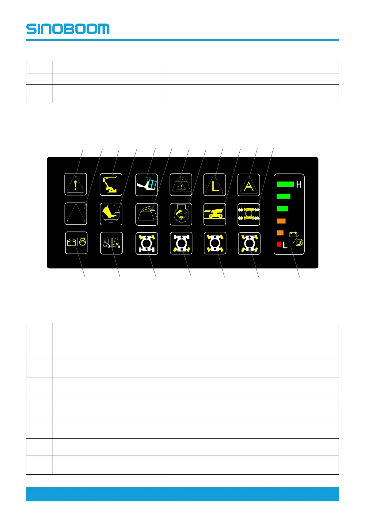
6.5 PLATFORM DISPLAY
Fig 5 Platform controller display
Table 6-5
No. Indication
Description
1
System fault indicator
This icon lights up to indicate low fuel level, low engine oil
pressure, high engine water temperature, CAN bus error, or
other faults.
2
Scope limiting indicator
This icon lights up to indicate that the boom is beyond the
specified working envelope.
3 Chassis tilt indicator
This icon lights up to indicate that the chassis tilt angle ex-
ceeds the maximum allowable tilt angle.
4 Foot switch indicator
This icon lights up to indicate that the foot switch is depressed.
5
Platform tilt indicator
This icon lights up to indicate that the platform is tilted.
6
Heavy load indicator
This icon lights up to indicate that the load on the platform ex-
ceeds the light load.
7 Overload alarm indicator
This icon lights up to indicate that the load on the platform ex-
ceeds its rated load.
8
High engine speed indicator
This icon lights up to indicate that the engine starts to run at
high speed.
DC
FE
Scope
1 2 3 4 5 6 7 8 9 10 11 12
1413 15 16 17 18 19