Do you have a question about the Sintrones VBOX-3600 and is the answer not in the manual?
Precautions to prevent electrical shock hazards during system setup and operation.
Guidelines to ensure safe operation and prevent damage to the product.
Details the system's CPU, memory, chipset, and other hardware specifications.
Provides a diagram and labels for the main board and system components.
Details the pin definition and connector map for the VGA JST connector.
Details the pin definition and connector map for the USB2 JST connector.
Details the pin definition and connector map for the USB1 JST connector.
Details the pin definition, wiring, and connector map for the GPIO JST connector.
Details the pin definition and connector map for the UART JST connector (COM5).
Details the pin definition and connector map for the LED1 JST connector.
Details the pin definition and connector map for the LED2 JST connector.
Details the pin definition and connector map for the COM3 JST connector.
Details the pin definition and connector map for the COM4 JST connector.
Details the pin definition and connector map for the AUDIO JST connector.
Details the pin definition and connector map for the SATA3 connector.
Details the pin definition and connector map for the SATA1 connector.
Details the pin definition and connector map for the SATA2 connector.
Details the pin definition for the Mini PCI-E slot (MiniCard1).
Details the pin definition for the Mini PCI-E slot (MiniCard2).
Details the pin definition for the Mini PCI-E slot (MiniCard3).
Details the pin definition for the Mini PCI-E slot (MiniCard4).
Details the pin definition, wiring diagram, and connector map for the power input.
Details the pin definition and connector map for the SATA power connector.
Details the pin definition and connector map for the UPS power connector.
Details the pin definition and connector map for USB3.0 Type A connectors.
Details the pin definition and connector map for another USB3.0 Type A connector.
Details the pin definition and connector map for the LAN1 RJ45 connector.
Details the pin definition and connector map for the LAN2 RJ45 connector.
Details the pin definition and connector map for the LAN3 RJ45 connector.
Explains M12 to RJ45 cable and defines M12 and CAT5 connector pin assignments.
Details the pin definition and connector map for the LAN4 RJ45 connector.
Details the pin definition and connector map for the DB29 (DVI-I) connector.
Details the pin definition and connector map for the Display Port connector.
Details the pin definition and connector map for the DB9 COM1 connector.
Details the pin definition and connector map for the DB9 COM2 connector.
Details the pin definition and connector map for the microphone input phone jack.
Details the pin definition and connector map for the line out phone jack.
Details the pin definition and wiring diagram for the ATX 6-pin power output connector.
Details the pin definition for the CAN BUS connector.
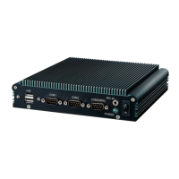
Provides an overview of the system's front and rear panel interfaces and components.
Provides step-by-step instructions with images for opening the device chassis.
Step-by-step guide on how to install RAM modules into the motherboard slots.
Instructions for installing a MINI PCIe expansion card into the PCIe 1 slot.
Instructions for installing a MINI PCIe expansion card into the PCIe 2 slot.
Instructions for installing a MINI PCIe expansion card into the PCIe 3 slot.
Instructions for installing a MINI PCIe expansion card into the PCIe 4 slot.
Step-by-step guide on connecting internal antenna cables using SMA connectors.
Provides instructions on how to insert a SIM card into the device.
Step-by-step guide for installing a Hard Disk Drive (HDD) into the device.
Detailed instructions and diagrams for installing the battery module.
Explains startup/shutdown conditions and procedures based on the ignition signal.
Covers GPIO configuration and delay time settings for system control.
Guides through configuring Super IO settings, including serial port modes.
Lists the included system components, mount bracket, screws, and cabling.
| USB Ports | 4 x USB 3.0 |
|---|---|
| Certification | CE, FCC, E-Mark |
| Operating System | Windows 10 |
| Video Output | 1x HDMI, 1x VGA |
| Serial Ports | 2 x RS-232/422/485 |
| Operating Temperature | 70°C |
| Power Input | 9-36V DC |
| SIM Card Slots | 1 |
| GPS | Optional |
| Audio | 1 x Mic-in, 1 x Line-out |
| Ignition Power Control | Yes, with configurable delay time |
| Wireless Connectivity | Wi-Fi 802.11 a/b/g/n/ac, Bluetooth 4.0 |