IDP-782 - Hardware Guide
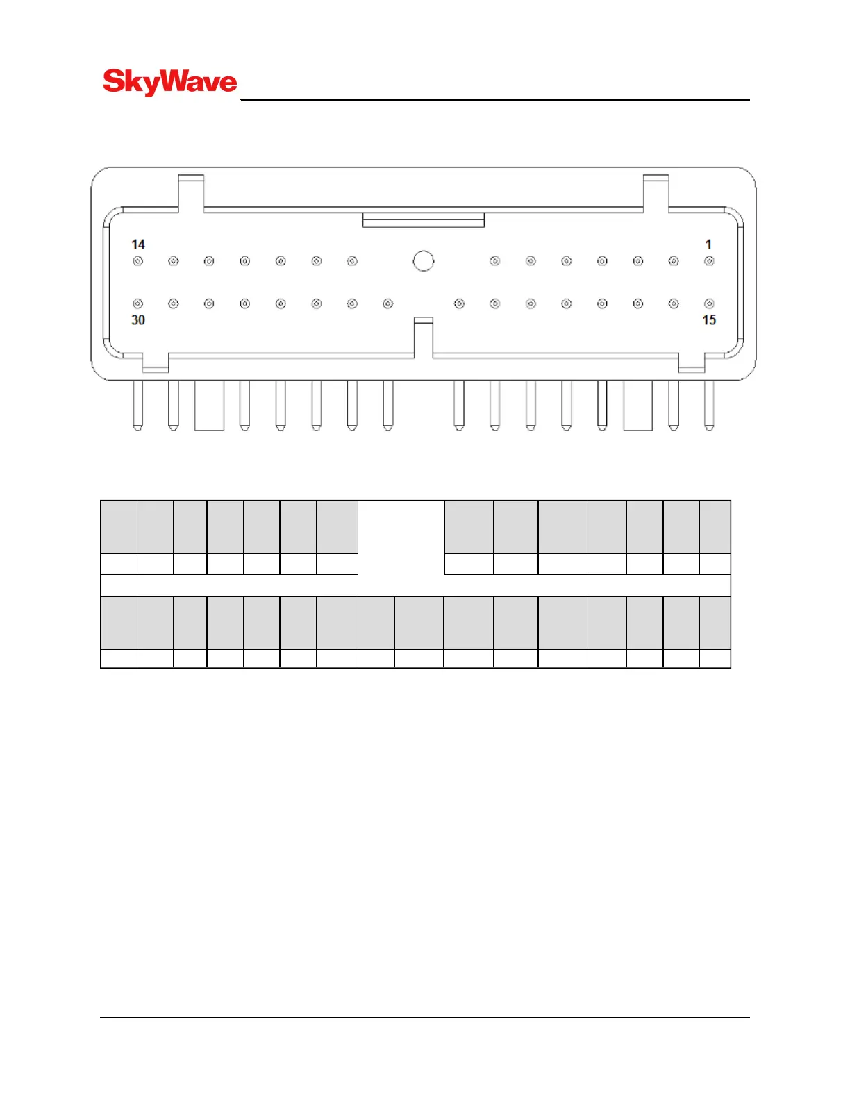
Figure 9: Transceiver View of Connector
Table 4: Electrical Pin Assignment
AUX_
RS232
_Rx
AUX_
RS232
_Tx
N/C Output
06
Output
05
N/C N/C MIC_B N/C SPK_B CAN_L RS485
_B
RS485
_A
SPK_
A
14 13 12 11 10 9 8 7 6 5 4 3 2 1
GND VIN I/O 04 I/O 03 I/O 02 I/O 01 Main_
RS232_
Tx
Main_
RS232
_Rx
MIC_A CAN_H 1_WIRE
_ COM
1_WIRE
_DATA
N/C N/C N/C N/C
30 29 28 27 26 25 24 23 22 21 20 19 18 17 16 15
3.4 Input/output Interface Specifications
The terminal supports four configurable I/Os (I/O 01 to I/O 04):
l Digital input with weak (1 MΩ) pull-down
l Digital input with 30-50 K pull-down
l Digital input with 30-50 K pull-up
l Analog input
l Digital output – push-pull
l Digital output – open drain switch-to-ground
l Disabled
I/O 01 can be used for ignition. Refer to 3.4.1
T213, Version 02
28
© SkyWave Proprietary