SMA Solar Technology AG 6 Connection
Installation Manual ClusterController-IA-en-10 53
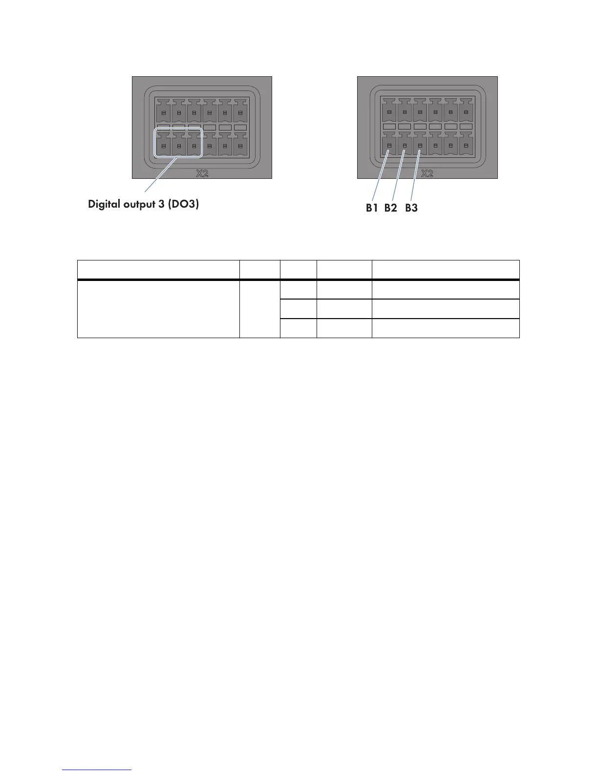
Figure21: Pin assignment at the terminal block Temperature output 3 (DO3)
1. Connect the connection cable to the remote terminal (see the manufacturer manual). For this
purpose, trim the unused insulated wires up to the cable shield and note the wire colours.
2. Connect the connection cable to the six-pole plug as follows:
• Depending on the remote terminal and the pin assignment at terminal block
Digital output 3 (DO3), identify the conductor entries that will be required for connecting
the connection cable.
• Release the required conductor entries using a screwdriver and insert the insulated wires into
the conductor entries. Observe the pin assignment.
3. Insert the six-pole plug at terminal X2 into pin row B.
4. On the connection cable, mark the terminal and pin row to which the connection cable is
assigned. For this purpose, use the cable ties with the caption field.
5. On the supplementary sheet for noting the connected devices, note the terminal to which the
remote terminal is assigned.
Connecting the Remote Terminal to the Analogue Current Output
Via the two analogue current outputs Analogue current output 1 (AO1) and Analogue current
output 2 (AO2), you can provide feedback on the value (if any) for the active power limitation or
the reactive power setpoint of the Cluster Controller that is currently being sent to the inverters in the
plant.
Requirements:
☐ The remote terminal must be able to receive a current signal in the range from 4 mA to 20 mA.
☐ The connection cable must have been prepared for connection to the multipole plug
(see Section 6.5).
Terminal block Relay Pin Signal Explanation
Digital output 3 (DO3)
Response contact for the current
active power limitation
CB1NC Back contact
B2 CO Change-over contact
B3 NO Front contact