6 Connection SMA Solar Technology AG
54 ClusterController-IA-en-10 Installation Manual
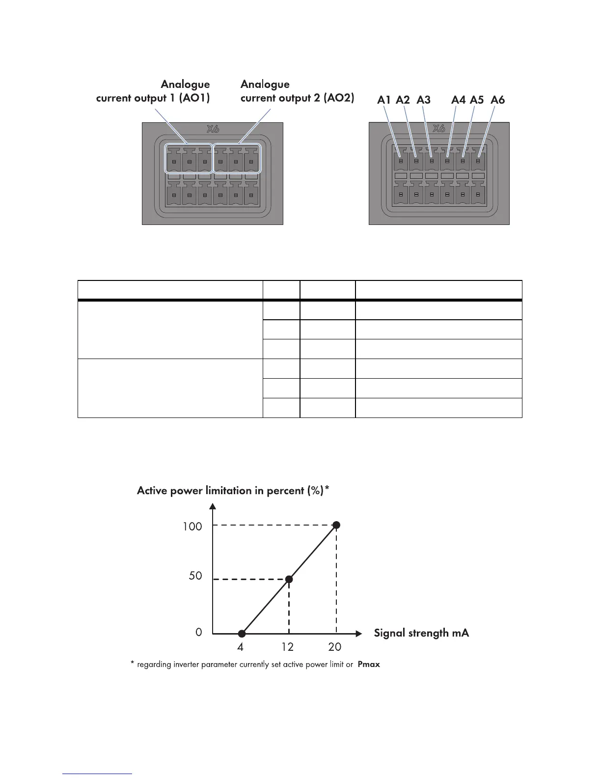
Figure22: Pin assignment at the terminal blocks Analogue current output 1 (AO1) and Analogue current
output 2 (AO2)
Interpretation of the Signal Strength as a Percentage Value of the Active Power Limitation
The strength of the feedback signal corresponds to the percentage value to which the active power
of the inverters in the plant is currently limited.
Figure23: Interpretation of the signal strength as a percentage value of the active power limitation in relation to
the inverter parameter Set active power limit or Pmax
Terminal block Pin Signal Explanation
Analogue current output 1 (AO1)
Feedback of the current active power
limitation
A1 I+ Current output
A2 I − Current feedback
A3 GND Shield ground
Analogue current output 2 (AO2)
Feedback of the current reactive power
setpoint
A4 I+ Current output
A5 I − Current feedback
A6 GND Shield ground