SMA Solar Technology AG 6 Connection
Installation Manual ClusterController-IA-en-10 55
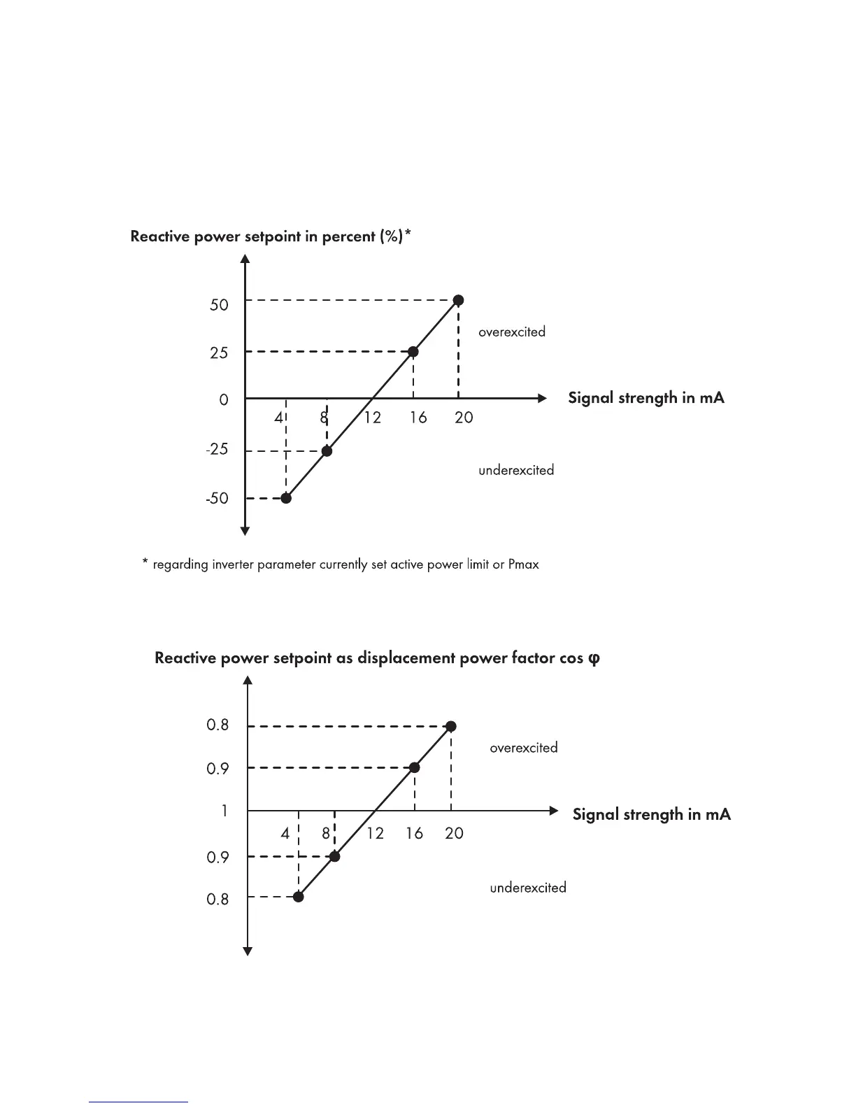
Interpretation of the Signal Strength as a Vale of the Reactive Power Setpoint
Depending on the size of the reactive power setpoint that was selected via the user interface
(see the Cluster Controller user manual), the strength of the feedback signal corresponds either to the
percentage value for the reactive power setpoint or to the latest displacement power factor cos φ sent
to the inverters in the plant.
Figure24: Interpretation of the signal strength as a percentage value of the reactive power setpoint in relation to
the inverter parameter Set active power limit or Pmax
Figure25: Interpretation of the signal strength as displacement power factor cos φ