HRX-OM-Q026
Chapter 5 Display and Setting of Various Functions
HRSH Series 5.5 Check Monitor Menu
5-11
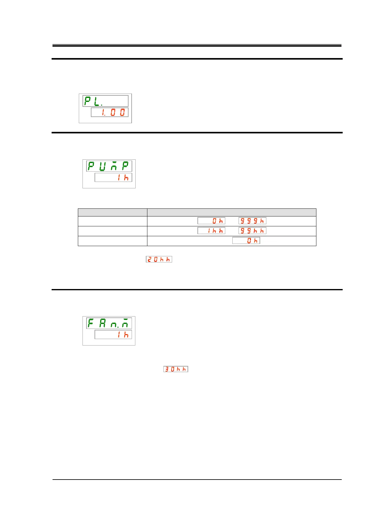
Checking: Refrigerant circuit pressure on the low pressure side
6. Press the [SEL] key once.
Display of the refrigerant circuit pressure on the low pressure side appears on the digital
display.
Checking: Accumulated operating time of the pump
7. Press the [SEL] key once.
Display of the accumulated operating time of the pump appears on the digital display.
Refer to the table below for details of the display.
Table 5.5-2 Time display
AL28 Pump maintenance alarm is generated when the accumulated operating time of the pump
reaches 20,000 hours ( ) (when set to “A.RUN”). For more details, refer to “Chapter 6
Alarm Notification and Troubleshooting”.
Checking: Accumulated operating time of the fan
8. Press the [SEL] key once.
Display of the accumulated operating time of the fan appears on the digital display.
Refer to “Table 5.5-2 Time display” for the display.
AL29 Fan maintenance alarm is generated when the accumulated operating time of the fan
motor reaches 30,000 hours ( ) (when set to “A.RUN”). For details, refer to “Chapter 6
Alarm Notification and Troubleshooting”.
 Loading...


