94
Scope Multimeter Operations Navigation
Navigation
The following section describes how to navigate the screen interface when viewing on the Display
Device. When using the Data Acquisition Device as a stand-alone test meter refer to "M2 Data
Acquisition Device Controls and Features‚" on page 19 for navigation instructions.
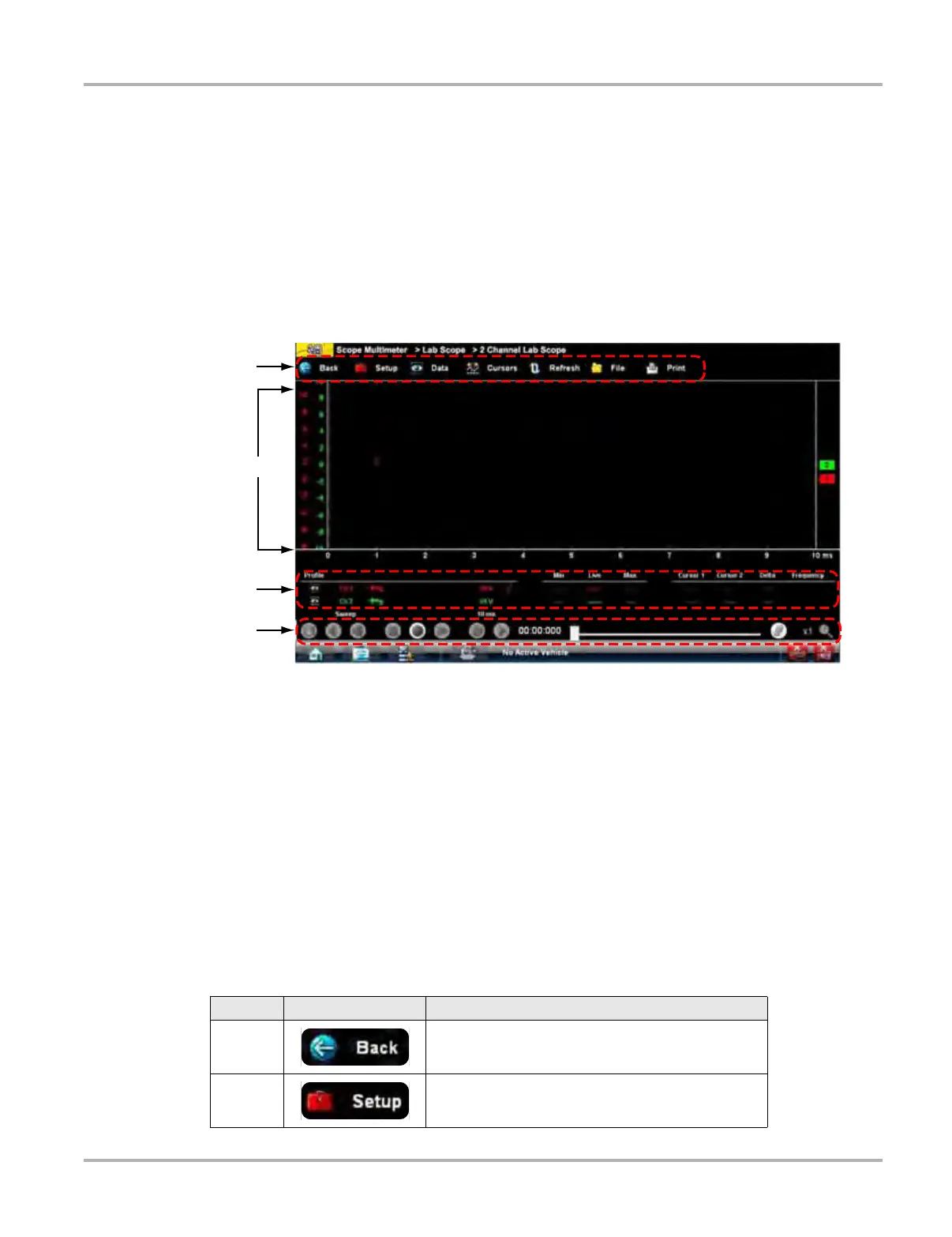
9.1.3 Screen Layout
The scope multimeter screens typically include the following sections (Figure 9-6):
1— Scope Multimeter toolbar—allows you to configure the tool for the type of test and to
adjust the settings for each channel, or trace.
2— Main body—displays test results. Options on the toolbar let you select how tests display
on the screen.
3— Trace Details—displays trace sampling conditions, which can be adjusted or switched
through the touch screen.
4— Record/Playback Control toolbar—allows you to record and navigate paused data
Figure 9-6 Scope Multimeter screen layout
Scope Multimeter Toolbar
The Scope Multimeter toolbar is used to set up the tool for testing and to configure the settings for
each trace. The table below gives brief descriptions of the control buttons on the toolbar:
Table 9-3 Scope Multimeter toolbar buttons (sheet 1 of 2)
Name Button Description
Back Returns to the previously viewed screen.
Setup
Opens a dialog box that allows you to select
personal preferences for viewing and saving data.