HYD 5/6/8/10/15/20KTL-3PH USER MANUAL
5.10.7 Communication power supply
The power supply can be used for the external power supply, or
for the switching contact. Max. 400 mA / 5 W.
5.10.8 CT Interface
For configurations according to System A, CTs are directly
connected to the inverter without an smart meter.
Please use the three CTs (3000:1) that come standard with the
attachment.
Customers can choose different CTs with different
primary currents according to the installation.
However, the secondary side current of Scheme A is
less than 100mA, while the secondary side current of
Scheme B is 5A. The lead length of CT cannot exceed 1
km;
After the customer chooses to install CTs with
different current specifications, he needs to set the
CT ratio (factory default 40:1) on the inverter.
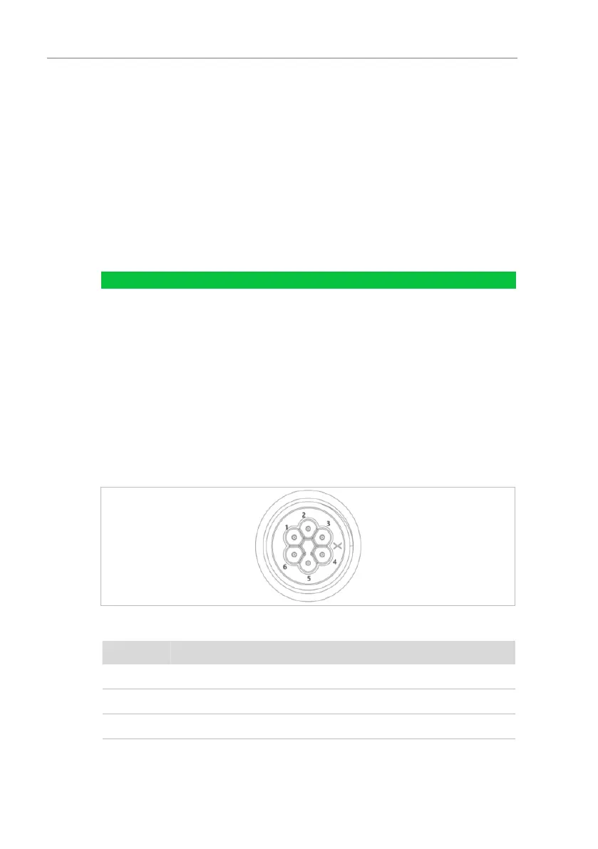
Please refer to the table below for the specific PIN connections.
Figure. 5-27 CT connection(a)
Table. 5-14 BMS interface description