PROFIBUS Tester 5 (BC-700-PB) - User Manual
24
Copyright 2016 Softing Industrial Automation GmbH
Cable test
The cable test assesses the wiring and can be used to determine a faulty cable location (e.g. short
circuit) by means of reflection test. All three features can only be used during shutdown of the
installation. The D-sub cable BC-600-PB-CB-DSUB-2 which is included in the standard scope of supply
must be used. As long as communication is detected on the bus, i.e. at least one device is an active
master, the functions are disabled. Check If necessary, disconnect every single active device (PLC, MPI
and, if necessary, diagnostic repeaters) from the power supply or the bus. If an active device is at the
end of the bus you want to test, its PROFIBUS connector needs to be unplugged and connected directly
to the PROFIBUS Tester 5 (BC-700-PB). The bus termination in the device connector will then be
powered by the BC-700-PB.
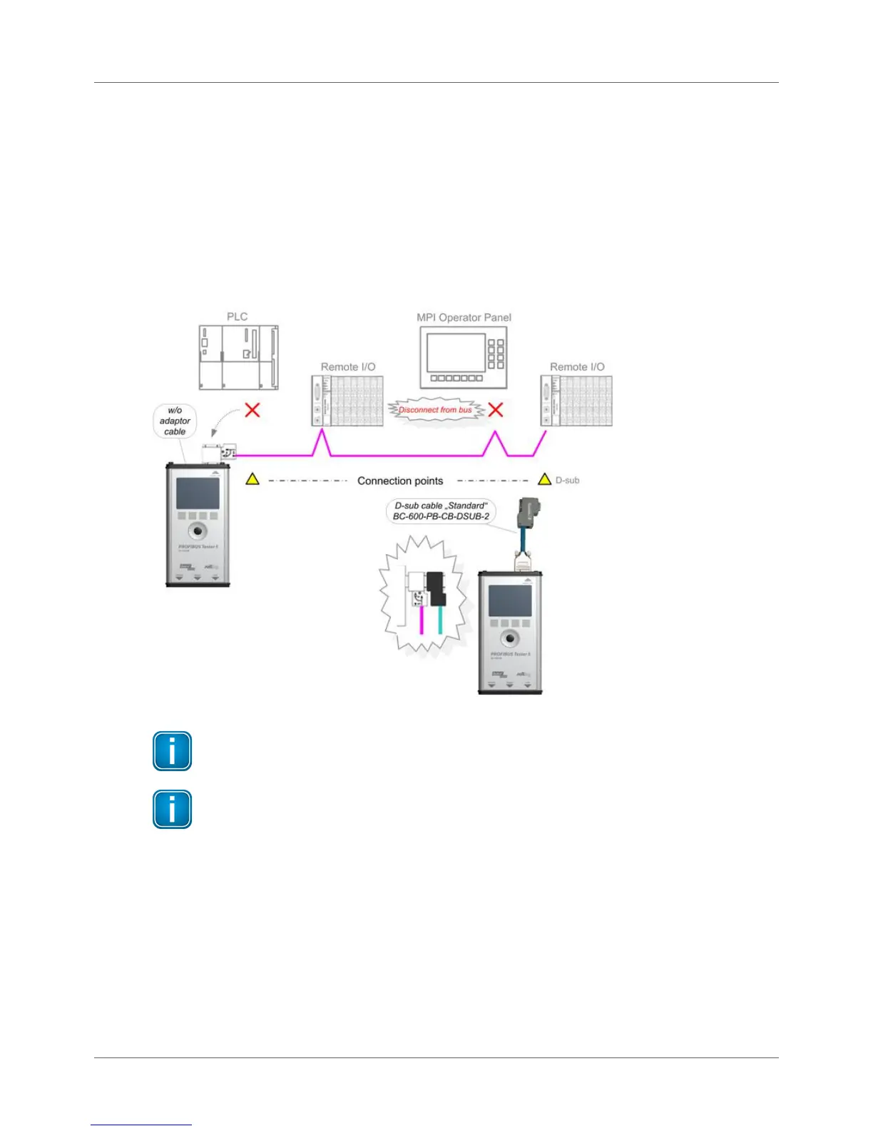
Figure 20: Connection points for topology scan and cable test
The three functions can be started also when the BC-700-PB is disconnected from the bus. If
you then connect the BC-700-PB to a live bus despite the yellow bus status bar indicated by
the PC software, this can cause bus communication problems or a shutdown of the
installation.
Special case: active devices at both ends o the bus during topology scan
On the very rare occasion when there is an active device at each end of the bus, do the following:
1. When using D-sub connection:
a. Additionally switch on the terminating resistor in the D-sub connector of the last slave.
b. Make sure the outgoing cable to the active device at the bus end is connected to the outgoing
connector (marked with "OUT", an outgoing arrow, or "A2/B2").