PROFIBUS Tester 5 (BC-700-PB) - User Manual
18
Copyright 2016 Softing Industrial Automation GmbH
3
Connection to PROFIBUS-DP
3.1 Basics
3.1.1 Note when testing a live bus
Test tool side effects
When you connect a test tool, side effects on the system under test are generally
unavoidable. If the PROFIBUS is already disturbed to a certain degree or if Simatic
Diagnostic Repeaters are used, the operation of the PROFIBUS might nevertheless be
affected occasionally. Observe the following connection notes.
3.1.2 Connection types
There are several ways to connect a bus station to a PROFIBUS network:
Using connectors
o D-sub connectors , most of which have an integrated terminating resistor and, optionally, an
additional service socket
o M12 connectors for environments requiring increased IP ratings
o Special vendor-specific hybrid connectors; they are used in combination with special cables to
supply power via the bus
Using terminals for direct connection
Due to the typical daisy-chain topology, the connection points of the bus stations are the only possible
points for connecting the test tool in most cases.
3.1.3 Adapter cable
The BC-700-PB is supplied with the D-sub adapter cable BC600-PB-CB-DSUB-2 Standard (light
connector). For testing on live systems the optional D-sub adapter cable BC-600-PB-CB-DSUB-2 is
recommended. An M12 adapter set is optionally available, see D-sub adapter cable for testing live
systems .
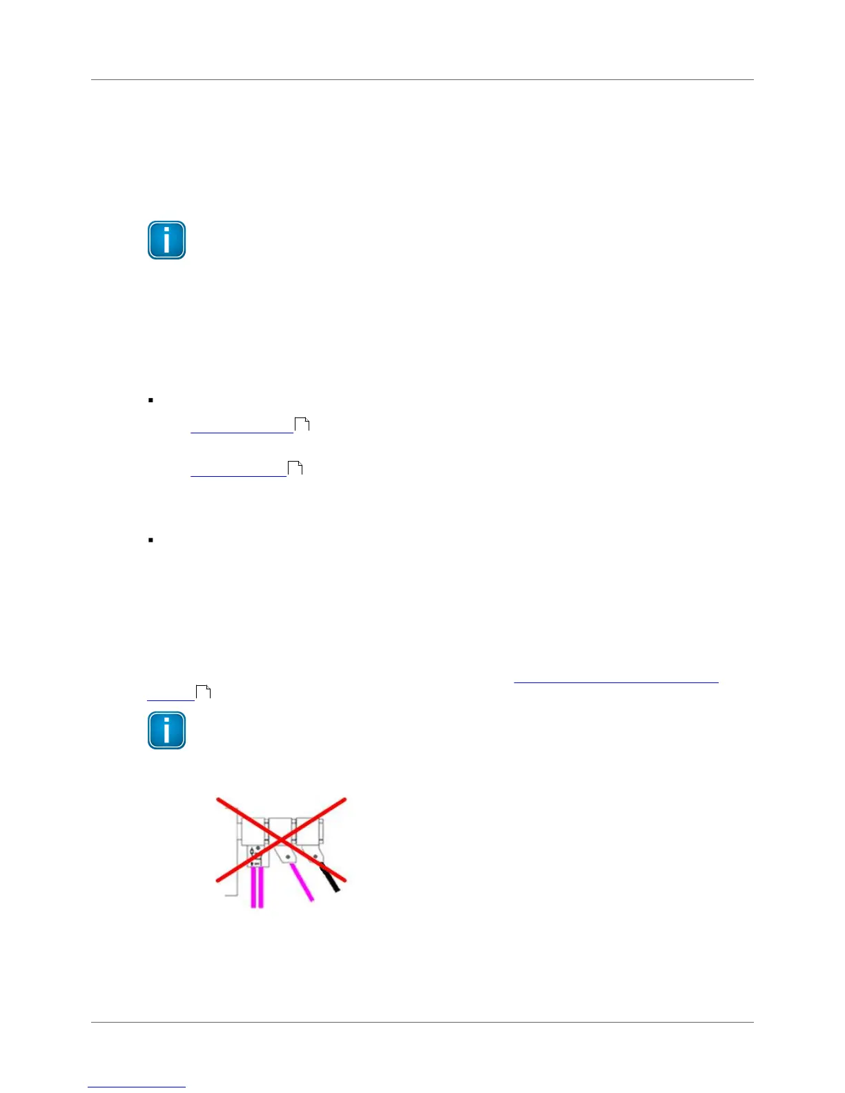
Only use original short cables
Use only the original short cables with special pin layout to connect the unit to a PROFIBUS
network. Do not cascade more than two D-sub connectors with service sockets at the same
time:
Figure 14: Unallowed cascading of D-sub connectors