7. PerformpairingasdescribedinActivating,CommissioningandConfiguringtheSystemUsingtheInverter
SetApponpage42.
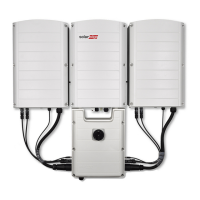
Replacing the Connection Unit
Removing the Connection Unit
1. TurnOFFtheInverterON/OFFswitch,andwaituntilthegreenLEDisblinking,indicatingthattheDC
voltageissafe(<50V),orwaitfiveminutesbeforecontinuingtothenextstep.
WARNING!
If you cannot see Primary Unit LEDs or you cannot connect to the Primary Unit, or if the red LED
light is on indicating a malfunction, wait five minutes for the input capacitors of the inverter to
discharge.
Si vous ne pouvez pas voir les LED de l'unité principale ou si vous ne pouvez pas vous connecter à
l'unité principale, ou si le voyant LED rouge s'allume, attendez cinq minutes que les condensateurs
d'entrée de l'onduleur se déchargent.
2. DisconnecttheACtotheinverterbyturningOFFthecircuitbreakersonthedistributionpanel.
3.
OpentheConnectionUnitcover:
l ReleasethesixAllenscrewsofthecover.
l Tiltthetopofthecovertowardsyou.
l Slidethecoverdownandremoveit.
CAUTION!
When removing the cover, make sure not to damage internal components. SolarEdge will not be held
responsible for any components damaged as a result of incautious cover removal.
Lors du retrait du couvercle, assurez-vous de ne pas endommager les composants internes. SolarEdge
ne peut être tenue pour responsable des composants endommagés à la suite d'une imprudence dans le
retrait du couvercle.
4. DisconnecttheinterlockandDCcables.
5. DisconnecttheSecondaryUnit(s)fromtheConnectionUnit.
6. IfyoureplaceaConnectionUnitwithabuilt-inEnergyMeter,disconnecttheRS485connectorfrom
theinvertercommunicationboard.
7.
UnscrewthetwoconduitnutsinthePrimaryUnitsecuringtheConnectionUnittoit,seeFigure52.
8. OpentheConnectionUnitcoveranddisconnecttheDC,ACandcommunicationwires.Unscrewthe
twoconduitnutssecuringtheConnectionUnittotheexternalconduits.
9. ReleasetheConnectionUnitbracketfromthewall.
10. CarefullyremovetheConnectionUnitwithitsmountingbracketfromthewall.
Installing a New Connection Unit
1. PositionthenewConnectionUnitbelowtheinverterandfromtheinsideofthePrimaryUnitgrab
theACandDCwiresextendingfromtheswitchconduits.
2. Securelyscrewthetwoconduitnutsontotheconduitendsintheinverter.
3. AttachtheConnectionUnitwithitsbrackettothewallandtightenitsscrew.
-Three Phase Inverter with Synergy Technology Installation MAN-01-00402-1.4
80
Replacing the Connection Unit