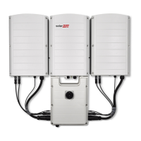
Connection Unit Interface
TheConnectionUnitispartofthePrimaryUnit.
NOTE
In the following figure the connections to the Secondary Unit are shown only on the left side of the
Connection Unit;for an inverter that has two Secondary Units, similar connections are located on the
other side of the unit as well.
Figure 13: Connection Unit bottom and side interface
l Safety switch:amanuallyoperatedsafetyswitchfordisconnectingtheDCpoweroftheSolarEdge
system.
NOTE
When the Connection Unit is OFF (for example during maintenance) it may be locked to prevent a
safety hazard:
1. Move the switch to the Lock position.
2. Insert the lock through the knob opening and lock.
l CablesforconnectiontotheSecondaryUnit(s):
o
CommuniationCable
o
DCCable
o
ACCable
l DC conduit entry:DCconduitforconnectingthePV
l DC drill guide:DCdrillguideforconnectingthePV
l AC drill guide entry :ACdrillguideforgridconnection
l Communication gland: forconnectionofcommunicationoptions.RefertoSettingUp
Communicationonpage57.
-Three Phase Inverter with Synergy Technology Installation MAN-01-00402-1.4
26
Connection Unit Interface

 Loading...