81
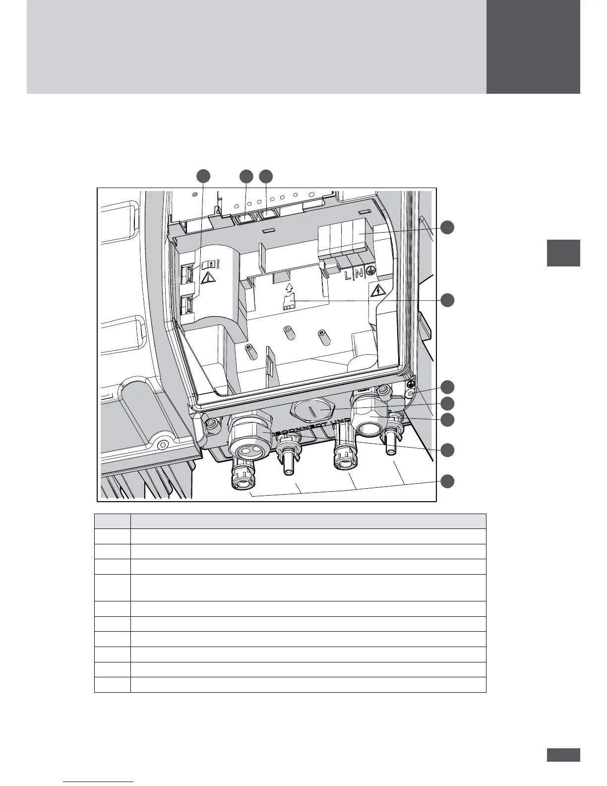
5.2 Connection area
The connection area with the cover removed and without contact protection.
10
9 8
7
6
5
4
3
2
1
No. Description
1 DC connections
2 Left-hand cable pass-through (multiple cable gland for the communication cables)
3 Right-hand cable pass-through (AC connection)
4 Locking screw (the locking screw is replaced by the cable gland when the I/O module
is installed)
5 Connection option for 2nd protective conductor
6 Slot for the optional I/O module
7 AC connection
8 RS485 socket
9 Ethernet socket
10 DC bridges for single tracking (tted ex works)