22
Section 4.6. A suitable M12 mating connector to connect to the status signalling contact
can be ordered from the SolarMax Service Centre.
Remote retrieval of the operating status can be congured, see Section 6.8.2.
Connecting conditions
V
Max
250VAC / 30VDC
I
Max
1.5A
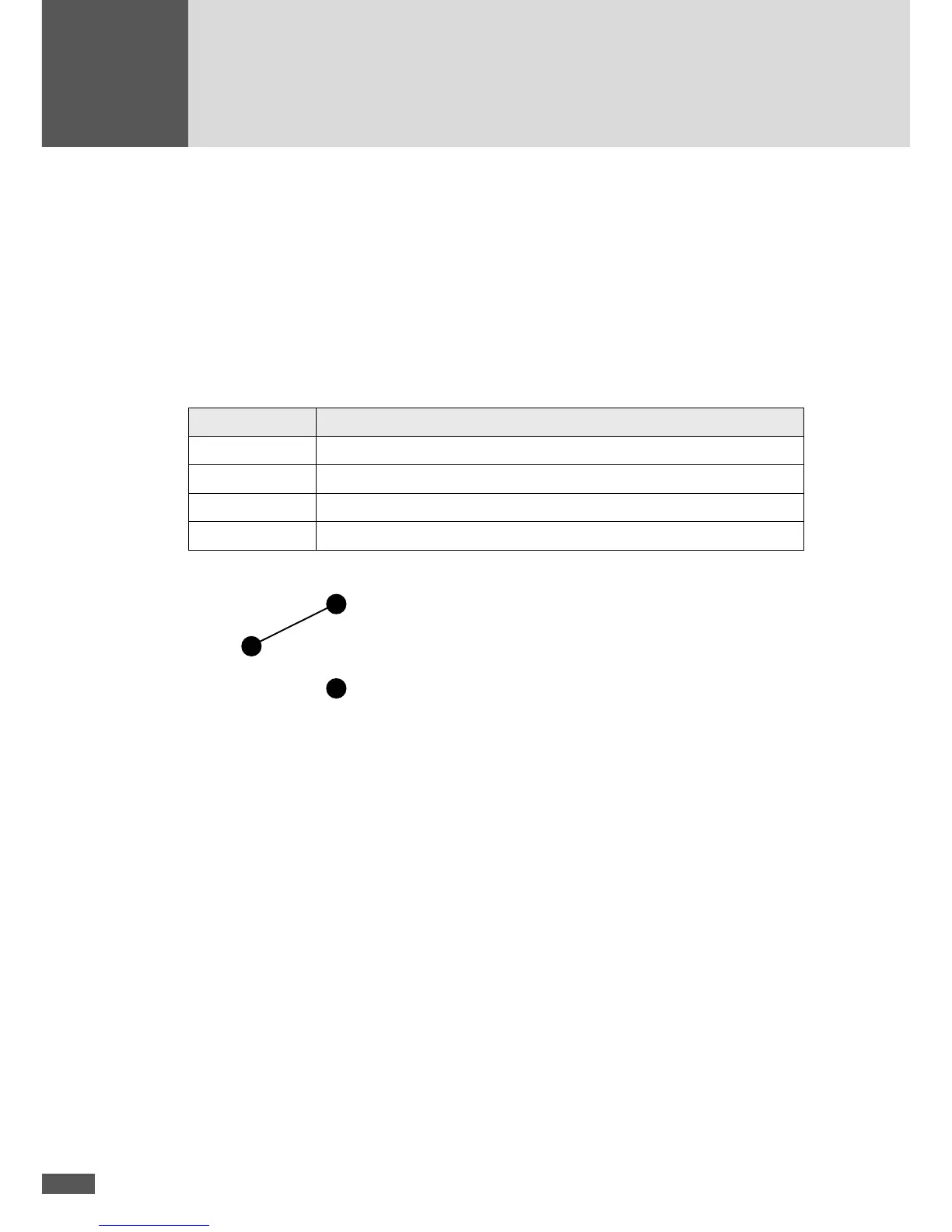
Pinout
Contact Description
1 NO (normally open: open when idle)
2 COM
3 NC (normally closed: closed when idle)
4 Not used
Contact diagram (idle)
NO
4.6.5 Monitoring external input
This interface can be used to connect the inverter to an external grid monitoring system
which will disconnect the inverter from the mains grid from a remote location when this
is needed.
If the “Monitoring external input” function is activated, the grid relays of the inverter can
be used as interconnection circuit breakers of the central G/P protection. The function
is activated during initial start-up (see Section 5.2) or subsequently using the service
software MaxTalk 2 Pro. Remote retrieval of the operating status, as described in Section
4.6.4, is no longer possible when monitoring of the external input is activated.
Functionality
The contacts 1 and 4 of the status signalling contact are used to monitor the external
input. When there is phase voltage between contact1 and contact4, the grid relays K1
and K2 are closed (see Section 3.3). If phase voltage is not present between contacts 1
and 4, the grid relays are open and the inverter disconnects from the grid.