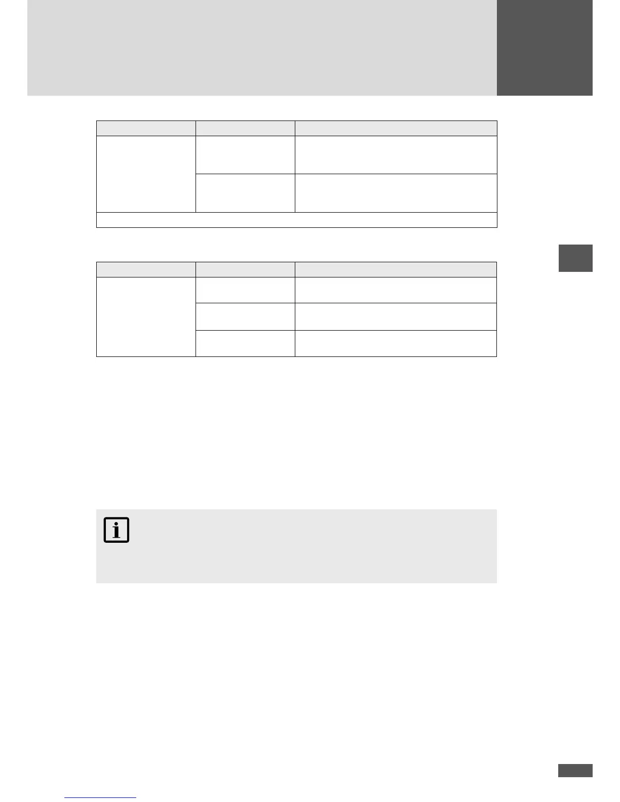
Menu Setting Description
Standard*
Guida Connessioni Required setting if the inverter is commissioned
within a PV plant connected to the grid before
1 July 2012.
CEI 0-21 Required setting if the inverter is commissioned
within a PV plant connected to the grid after 30
June 2012.
* the menu is only displayed at the “Low-voltage” grid connection.
Country setting “Spain”
Menu Setting Description
Standard RD 1699
The inverter is connected to the low-voltage
grid.
RD 1699 & PO 12.3 -
Large PV Systems
The inverter is connected to the low-voltage
grid. The FRT function is activated.
RD 661 & PO 12.3
The inverter is connected to the medium-volt-
age grid. The FRT function is activated.
5.3 Conguration of the data communication interfaces
In order to use the RS485 and Ethernet communications interfaces, you must enter the
following settings in the “Settings” menu (see Section 6.8):
Device address
If you connect several inverters into one network, you must assign each device its own
address.
NOTE
You can assign addresses between 1 and 249. It is very important to remember to give
a unique address to each individual device in the network!
When connecting to a LAN network, the following settings are required in addition to the
device address:
Ethernet
If you want to operate the right RJ45 communications socket on the terminal block as an
Ethernet interface, enter “on” at this point.
IP
If you want to access your inverter from a local area network (LAN), enter an unassigned
IP address from your LAN here.
 Loading...