157
Appendix
+
-
+
-
Meter/CT
Parallel 1Parallel 2 Parallel 1Parallel 2
CAN
Inverter
Master
Inverter
Slave
PV+ PV- Battery
PV+ PV- Battery
PE PE PE
PE
Meter
R RS T N S T N
Grid EPS
Grid EPS
R
S
T
N
Three-phase
Normal Load
Three-phase
Normal Load
Single-phase
Normal Load
Single-phase
Normal Load
Single-phase
Normal Load
R
S
T
N
NLR S T N
NL
NL
RSTN
Grid
R S T N
R S T N
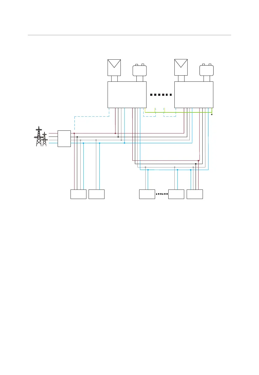
Figure 15-18 System diagram without SolaX X3-Parallel EPS BOX
Detailed parallel system
①
Power cable connection - Grid and EPS terminals
• Parallel connection with X3-Parallel EPS BOX.
»
Connect the master and slave inverters, as well as the X3-Parallel EPS BOX,
using five-core copper wires.
»
Connect L1 of the Grid terminal in the master and slave inverters, and X3-
Parallel EPS BOX together. Similarly, connect L2 with L2, L3 with L3, and N
with N.
»
Connect L1 of the EPS terminal in the master and slave inverters, and X3-
Parallel EPS BOX together. Similarly, connect L2 with L2, L3 with L3, and N
with N
»
Connect the PE wires of all inverters to the same E-Bar, preferably located
nearby.
 Loading...


