48
Electrical Connection
+
-
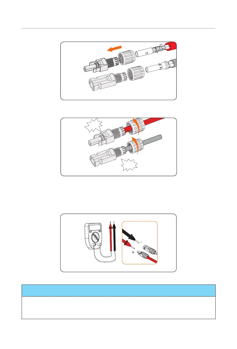
Figure 7-17 Threading the PV cable
+
-
Click!
Click!
Figure 7-18 Securing the PV cable
Step 4: Use a multimeter to measure the positive and negative voltage of the assembled
PV connectors. Make sure the open circuit voltage does not exceed the input
limit of 1000 V.
+ -
Figure 7-19 Measuring the voltage of PV connectors
NOTICE!
• If the voltage reading is negative, it indicates an incorrect DC input polarity. Please
check if the wiring connections on the multimeter is correct or PV connectors are
not mistakenly connected.

 Loading...


