1-3
DNW-A220
DNW-A220P
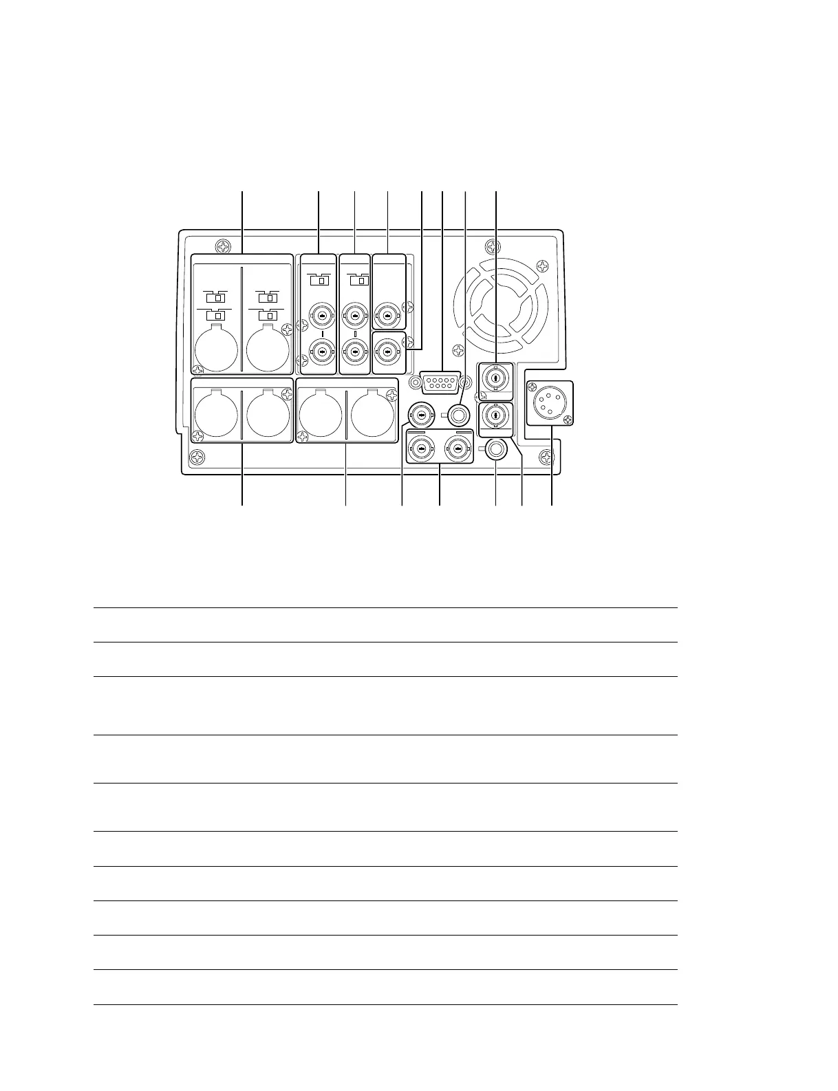
1-3. Connector Input/Output signals
The left and right connector panels of the unit are provided with the same input/output connectors.
Communications connectors
6 REMOTE D-SUB 9P connector x 1 (RS-422A interface)
Remote control
![ AUX 6-pin connector x 1
Input connectors
1 AUDIO INPUT CH-1/CH-2 XLR 3-pin x2
Analog audio 2 channels
_60 dBu, 0 dBu, +4 dBu selectable, high impedance, balanced
2 VIDEO REF.IN BNC x2 (In loop through connection, with 75 Z termination switch)
External reference video signal (Black burst or composite sync)
40 IRE/0.3 Vp-p, 75 Z, negative sync
3 VIDEO INPUT BNC x2 (In loop through connection, with 75 Z termination switch)
Analog composite video 1.0 Vp-p, 75 Z, negative sync
!- SDI IN BNC x1
Component digital (270 Mbit/s) SMPTE 259M/ITU-R BT.656
8 TC IN BNC x1
Time code 0.5 to 18.0 Vp-p, 10 kZ, unbalanced
!\ DC IN XLR 4-pin x1
DC +11 to 17 V
BATTERY IN 5-pin terminal x1
(on battery sub panel) Lithium-ion battery interface
REMOTE
TC IN
TC OUTSDI OUT
SDI IN DC OUT
DC-IN
AUX
12
VIDEOAUDIO INPUT
REF.
IN
AUDIO OUTPUT
ONOFF
75Z
ONOFF
CH-1
1/3
+48V
+4dBu_60 0
ONOFF
CH-2
+48V
+4dBu_60 0
INPUT OUTPUT
ON
1
2(SUPER)
OFF
75Z
2/4
MONITOR OUTPUT
R L
1
9 !/ != ![ !\!]!-
2 3 4 6 875
〈 Connector panel 〉
1-3. Connector Input/Output signals
 Loading...