4-13
DNW-A220
DNW-A220P
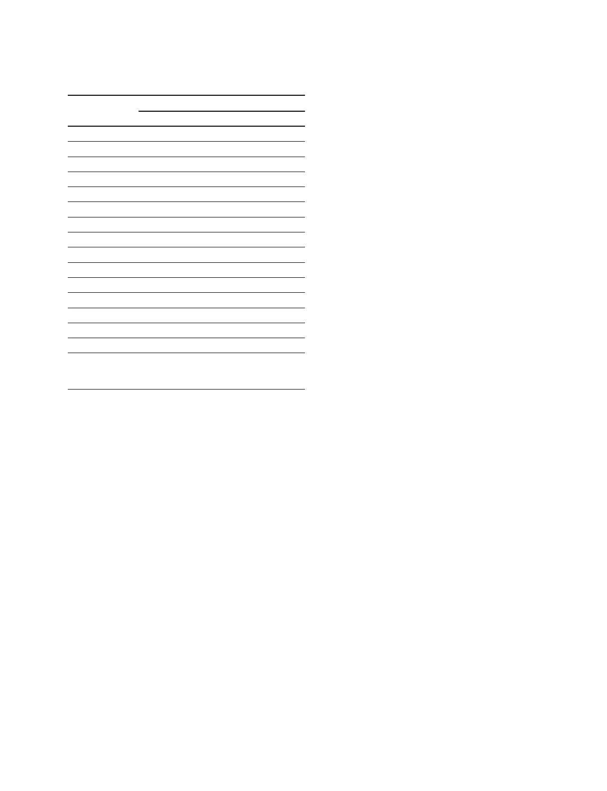
This table is in measure order of the heads.
Head Spec. Head tip protrusion (Hr = Hb _ Ha)
name (µm)
First time Second time
CNF A 20 = _ |=_
CNF B 20 = _ |=_
Y-A
*
20 = _ |=_
C-A
*
20 = _ |=_
ADV A2 20 = _ |=_
ADV B2 20 = _ |=_
Dummy _ (No need for measurement)
Erase _ (No need for measurement)
REC A 20 = _ |=_
REC B 20 = _ |=_
Y-B
*
20 = _ |=_
C-B
*
20 = _ |=_
ADV A1 20 = _ |=_
ADV B1 20 = _ |=_
Dummy _ (No need for measurement)
* : For player section of DNW-A220 and DNW-A25 exclusive use.
Removal of Head Tip Protrusion Measurement
Gauge
1. Rotate the upper drum manually counterclockwise (3)
very slowly to move a video head aside from the
probe.
2. Loosen the adjustment screw of the measurement
gauge fully by turning it counterclockwise.
3. Lift up the positioning flange from the outer circum-
ference of the drum’s upper surface to a few millime-
ters, and then lift the measurement gauge slowly and
remove it while pushing two legs against the outer
circumference of the drum’s upper surface (applying
force slightly to the measurement gauge in the direc-
tion indicated by arrow A). (Refer to Figure 3.)
n
Perform carefully and slowly so that the probe of a
measurement gauge does not contact the outer circum-
ference or video heads on the drum.
4-4. Video Head Tip Protrusion Check