2-2
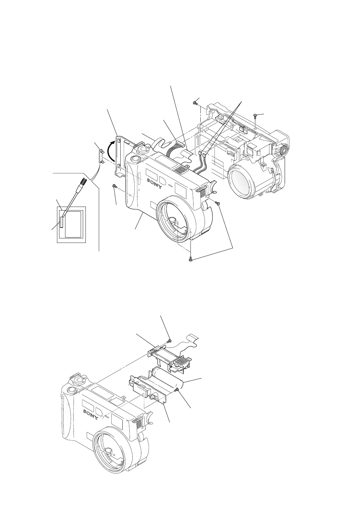
2-2. LCD HOLDER AND FLASH UNIT
1 Screw (1.7 × 4)
2 LCD holder block
3 Two screws
(1.7 × 4)
4 Flash unit
Note: Do not touch the capacitor terminals.
You could get an electric shock.
Capacitor
Note: Follow the disassembly procedure in the numerical order given.
2-1. FRONT CABINET BLOCK ASSEMBLY
1 Open the battery
lid assembly.
7 Flexible
board
(CN707)
8 Connector
(CN706)
9 Flexible board
(FP-031 flexible board)
3 Two screws
(2 × 4)
0 Two connectors
(CN710, 712)
4 Screw
(2 × 4)
2 Screw
(2 × 4)
6 Front cabinet
block assembly
5 Three screws
(2 × 4)
qa CPC lid
Note: In removing the CPC lid,
start form the upper side.
BT holder
assembly
CPC lid
 Loading...