5-25
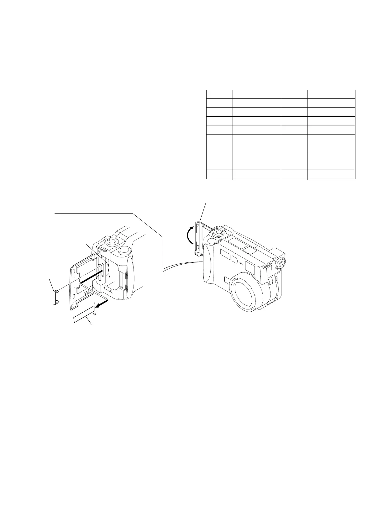
Fig. 5-1-19
[Adjusting connector]
Most of the measuring points for adjusting the LCD system are
concentrated in CN709 of the SY-58 board.
Connect the Measuring Instruments via the CPC-9 jig (J-6082-
393-C).
The following table shows the Pin No. and signal name of CN709.
Pin No. Signal Name Pin No. Signal Name
1 N. C. 10 UNREG
2 N. C. 11 LANC IN
3 N. C. 12 LANC OUT
4 REG GND 13 N. C.
5 XCPC_IN 14 RF7
6 N. C. 15 TXD
7 HSY 16 RXD
8 PANEL COM 17 RESET
9 VG 18 VDD
Table 5-1-7
• ATTACHMENT OF CPC-9 JIG
SY-58 board
(CN709)
CPC lid
Open the battery
lid assembly.
CPC-9 jig (J-6082-393-C)
(18P flexible board)
Note 1: Don’t use the 12 pin flexible board of CPC-9 jig.
It causes damage to the unit.
Note 2: In removing the CPC lid, start from
the upper side.
Note 3: The old CPC-9 jig (Parts code: J-6082-303-B) cannot be used,
because it cannot operate the adjustment remote commander.
1-5. LCD SYSTEM ADJUSTMENTS
Before perform the LCD system adjustments, check that the
specified values of “VIDEO SYSTEM ADJUSTMENTS” are sat-
isfied.
Note 1: The back light (fluorescent tube) is driven with high volt-
age AC power. Therefore, do not touch the back light
directly, otherwise you will feel an electric shock.
Note 2: Taken an extreme care not to destroy the liquid crystal
display module by static electricity when replacing it.
Note 3: Set the LCD BRIGHT to the center.