5-29
Fig. 5-1-24
A
2H
Fig. 5-1-25
A
A
A
A
B
B
B
B
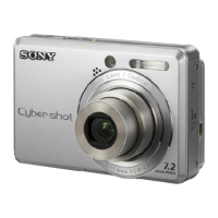
7. V-COM Level Adjustment (PD-128 Board)
Set the common electrode drive signal level of LCD to the speci-
fied value.
Mode PLAY
Signal Arbitrary
Measurement Point Pin 8 of CN709 (PANEL COM)
on SY-58 board
Measuring Instrument Oscilloscope
Adjustment Page D
Adjustment Address D6
Specified Value A = 6.50 ± 0.05 Vp-p
Adjusting method:
1) Select page: 0, address: 01, and set data: 01.
2) Select page: 5, address: F1, and set data: 03.
3) Select page: D, address: D6, change the data and set the V-
COM signal level (A) to the specified value.
4) Press the PAUSE button of the adjusting remote commander.
Processing after Completing Adjustments:
1) Select page: 5, address: F1, and set data: 00.
2) Select page: 0, address: 01, and set data: 00.
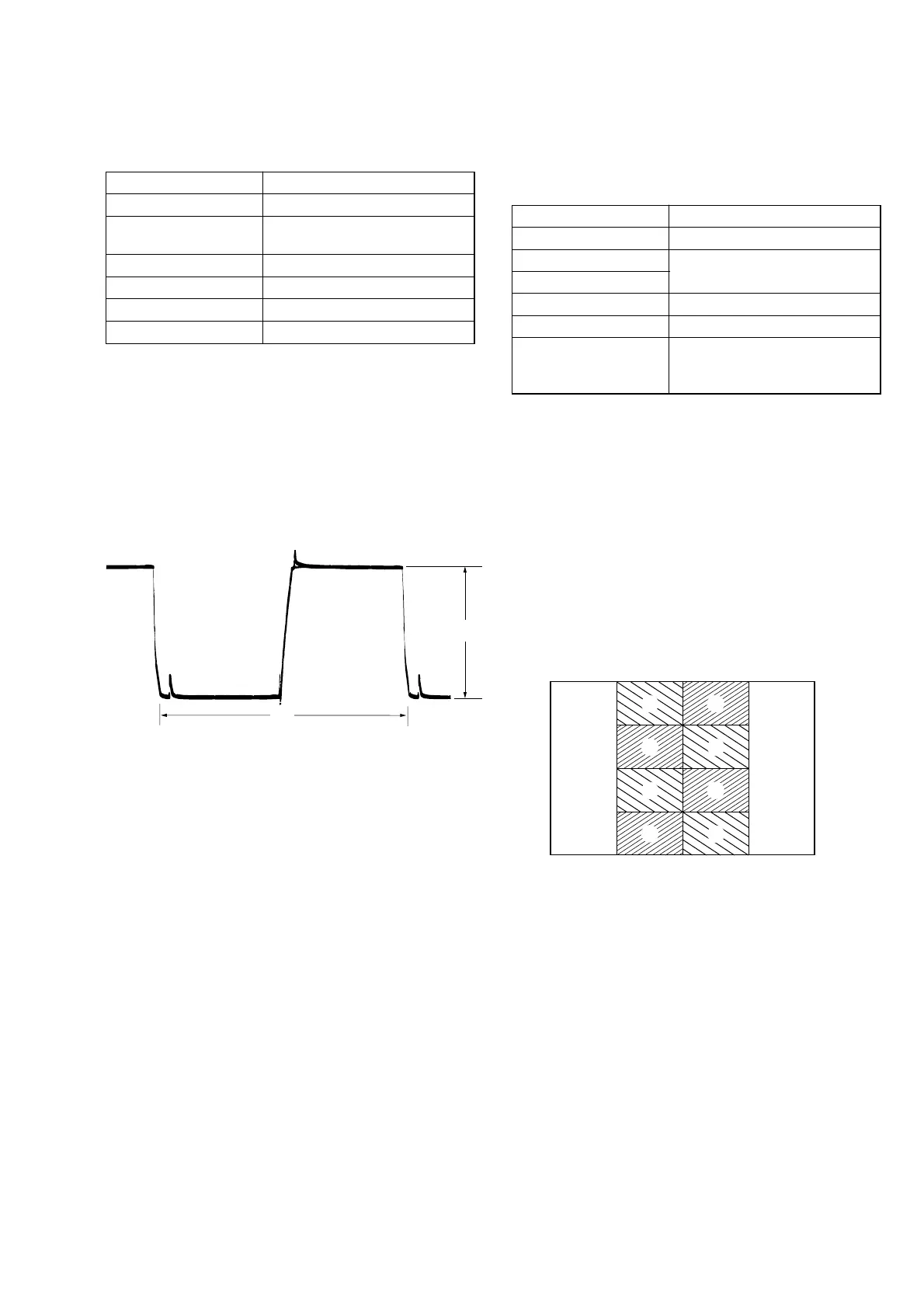
8. V-COM Adjustment (PD-128 Board)
Set the DC bias of the common electrode drive signal of LCD to
the specified value.
If deviated, the LCD display will be move, producing flicker and
conspicuous vertical lines.
Mode PLAY
Signal Arbitrary
Measurement Point Check on LCD screen
Measuring Instrument
Adjustment Page D
Adjustment Address D8
Specified Value The brightness difference
between the section-A and
section-B is minimum
Note: Perform “Bright Adjustment” and “Contrast Adjustment”
before this adjustment.
Adjusting method:
1) Select page: 0, address: 01, and set data: 01.
2) Select page: 5, address: F1, and set data: 01.
3) Select page: 2, address: 10, and set data: 02.
4) Select page: D, address: D8, change the data so that bright-
ness of the section A and section B is equal.
5) Press the PAUSE button of the adjusting remote commander.
Processing after Completing Adjustments:
1) Select page: 5, address: F1, and set data: 00.
2) Select page: 2, address: 10, and set data: 00.
3) Select page: 0, address: 01, and set data: 00.