5-22
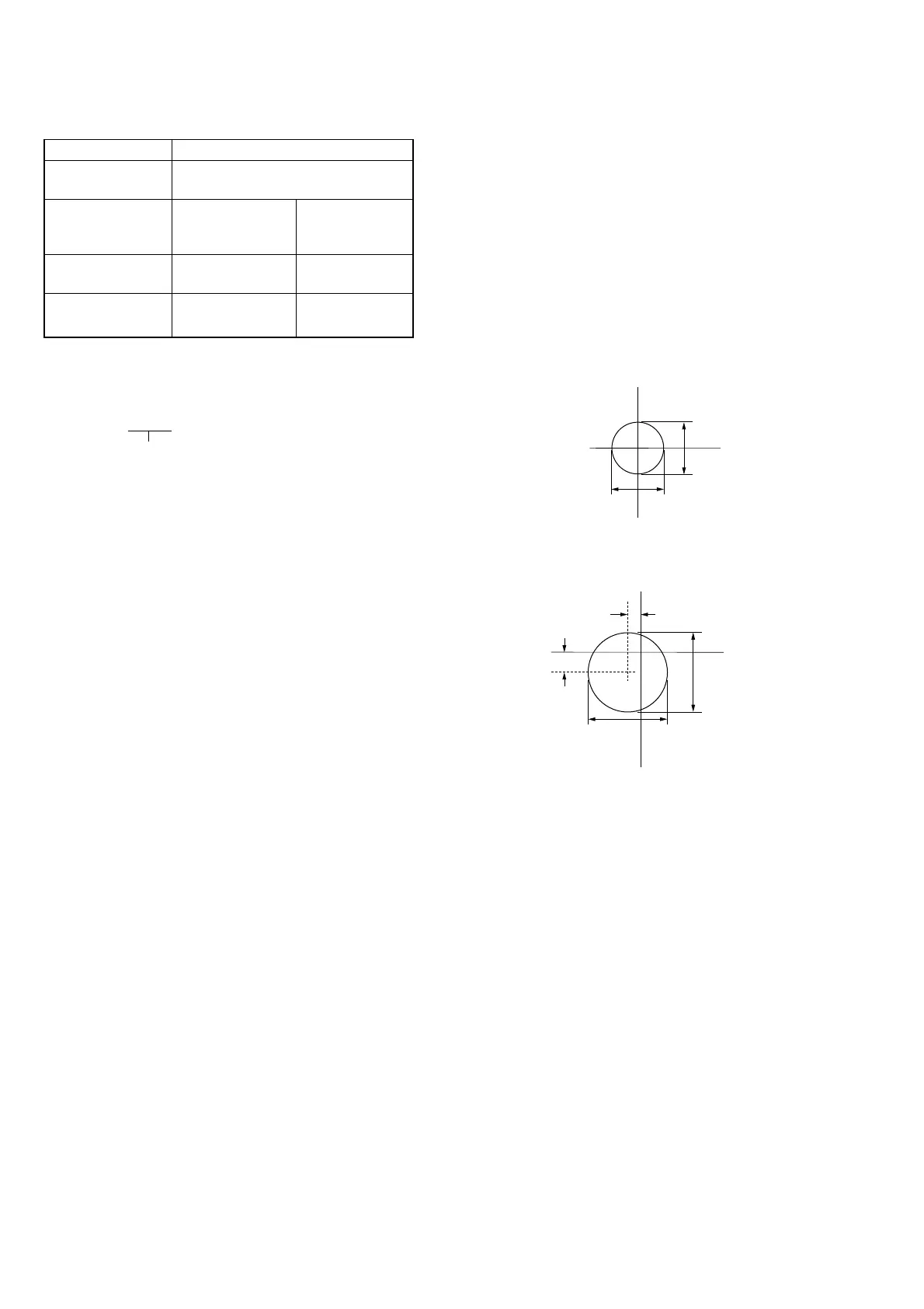
Fig. 5-1-18 (A)
Fig. 5-1-18 (B)
R-Y
B-Y
1.5mm
1mm
6mm
6mm
12. White Balance Check
Mode STILL
Subject Clear chart
(Color reproduction adjustment frame)
Measurement Point Displayed data of Video terminal of
Page: 1 (Note 2) A/V OUT jack
(75 Ω terminated)
Measuring Instrument Adjustment remote Vectorscope
Commander
Specified Value R ratio: 3E00 to 4200 Fig. 5-1-18
B ratio: 3E00 to 4200 (A) and (B)
Note 1: Refer to “6. Picture Frame Setting” for XH, XL, YH and
YL.
Note 2: The right four digits of the page: 1 displayed data of the
adjusting remote commander.
1:XX:XX
Displayed data
Checking method:
1) Check that the lens is not covered with either filter.
2) Select page: 0, address: 01, and set data: 01.
3) Select page: 5, address: F1, and set data: FF.
4) Select page: D, address: 63, set data: 40, and press the PAUSE
button of the adjusting remote commander.
5) Perform “ Data setting during camera system adjustment”.
(Refer to page 5-13)
6) Select page: 6, address: 90, and set data: XL. (Note 1)
7) Select page: 6, address: 91, and set data: XH. (Note 1)
8) Select page: 6, address: 92, and set data: YL. (Note 1)
9) Select page: 6, address: 93, and set data: YH. (Note 1)
10) Select page: 6, address: 6C, and set data: 01.
11) Select page: 6, address: 01, set data: 79, press the PAUSE
button, and wait for 1 second.
12) Select page: 6, address: 2C, and set data: 01.
• INDOOR data check
13) Select page: E, address: 52, after noting down the data, set
data: 0E, and press the PAUSE button.
14) Select page: 6, address: 01, set data: 0F, and press the PAUSE
button.
15) Select page: 0, address: 03, and set data: 04.
16) Select page: 1, and check that the displayed data (Note 2)
satisfies the R ratio specified value.
17) Select page: 0, address: 03, and set data: 05.
18) Select page: 1, and check that the displayed data (Note 2)
satisfies the B ratio specified value.
• INDOOR luminance point check
19) Select page: 6, address: 1C, and set data: 00.
20) Select page: 0, address: 03, and set data: 00.
21) Check that the center of the white luminance point is within
the circle shown Fig. 5-1-18 (A).
• OUTDOOR luminance point check
22) Place the C14 filter on the lens.
23) Select page: E, address: 4B, after noting down the data, set
data: 20, and press the PAUSE button.
24) Select page: 6, address: 01, set data: 3F, and press the PAUSE
button.
25) Check that the center of the white luminance point settles in
the circle shown Fig. 5-1-18 (B).
Processing after Completing Adjustments:
1) Select page: 6, address: 01, set data: 00, and press the PAUSE
button of the adjusting remote commander.
2) Select page: 6, adderss: 6C, and set data: 00.
3) Select page: E, address: 52, set data noted down at step 13)
and press the PAUSE button.
4) Select page: E, address: 4B, set data noted down at step 23)
and press the PAUSE button.
5) Select page: 5, address: F1, and set data: 00.
6) Select page: D, address: 63, set data: 00, and press the PAUSE
button.
7) Release the data setting performed at step 5).
(Refer to page 5-13)
8) Select page: 0, address: 01, and set data: 00.