5-17
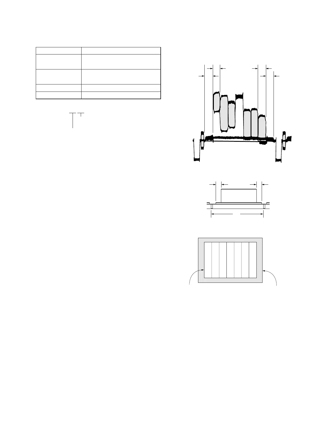
5. Picture Frame Setting
Mode STILL
Subject Color bar chart
(Color reproduction adjustment frame)
Measurement Point Video terminal of A/V OUT jack
(75 Ω terminated)
Measuring Instrument Oscilloscope and TV monitor
Specified Value A=B, C=D, E=F
Check on the oscilloscope
1. Horizontal period
Fig. 5-1-13
2. Vertical period
Fig. 5-1-14
Check on the TV monitor
Fig. 5-1-15
A=B
C=D
A
B
C
D
Color bar chart picture frame
TV monitor picture frame
Note 1: Displayed data of page 1 of adjusting remote commander.
1:XX:XX
XL or YL data
XH or YH data
Setting method:
1) Select page: 5, address: F1, and set data: FF.
2) Perform “ Data setting during camera system adjustment”.
(Refer to page 5-13)
3) Adjust the zoom and the camera direction, and set to the pic-
ture frame to the specified position.
4) Mark the position of the picture frame on the TV monitor,
and adjust the picture frame to this position in following ad-
justments using “Color reproduction adjustment frame”.
5) Select page: 0, address: 03, and set data: 18.
6) Select page: 1, and note down the XH and XL data. (Note 1)
7) Select page: 0, address: 03, and set data: 22.
8) Select page: 1, and note down the YH and YL data. (Note 1)
9) Release the data setting performed at step 2).
(Refer to page 5-13)
10) Select page: 5, address: F1, and set data: 00.
How to reset the zoom and focus when they deviated:
If the zoom and focus deviated due to some reason, reset them in
the following method.
1) Select page: 6, address: 90, and set data: XL. (Note 2)
2) Select page: 6, address: 91, and set data: XH. (Note 2)
3) Select page: 6, address: 92, and set data: YL. (Note 3)
4) Select page: 6, address: 93, and set data: YH. (Note 3)
5) Select page: 6, address: 01, set data: 79, press the PAUSE
button, and wait for 1 second.
6) Select page: 6, address: 2C, and set data: 01.
7) Select page: 6, address: 01, set data: 00, and press the PAUSE
button.
Note 2: The data noted down at step 6) of “Setting method”.
Note 3: The data noted down at step 8) of “Setting method”.
 Loading...