5-31
1-6. SYSTEM CONTROL SYSTEM ADJUSTMENTS
1. Battery Down Adjustment
Set the battery end voltage.
If the voltage is incorrect, the life of battery will shorten.
The image at the battery end will also be rough.
Mode STILL
Subject Arbitrary
Measurement Point Displayed data of page: 2,
address: 51
Measuring Instrument Adjusting remote commander
Adjustment Page D
Adjustment Address 90 to 94
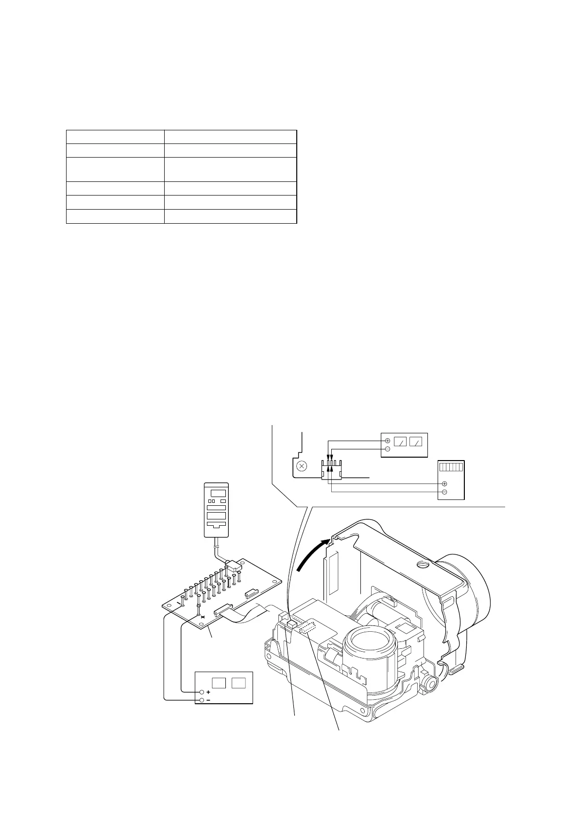
Connection:
1) Connect the regulated power supply and the digital voltmeter
to the battery terminal as shown in Fig. 5-1-26.
Fig. 5-1-26
MS-54
board
SY-58 board
(CN709)
CPC-9 jig
(J-6082-393-C)
DC power supply
(6.0 to 7.2 V DC)
Adjustment remote
commander
CN101
Regulated power supply
(5.50 ± 0.1 V DC)
Digital
voltmeter
1
2
18
1
18
1
Note : The old CPC-9 jit (Parts code: J-6082-393-B)
cannot be used, because it cannot operate
the adjustment remote commander.
Adjusting method:
1) Adjust the output voltage of the regulated power supply so
that the digital volt meter display is 7.2 ± 0.1 Vdc.
2) Turn off the power supply.
3) Turn the HOLD switch of the adjusting remote commander.
4) Turn on the power supply.
5) Insert the memory stick to the unit, and set the STILL mode.
6) Set the FOCUS switch in MANUAL mode.
7) Select page: 0, address: 01, and set data: 01.
8) Decrease the output voltage of the regulated power supply so
that the digital voltmeter display is 5.50 ± 0.01 Vdc.
9) Select page: 2, address: 51, read the data, and this data is named
Dref.
10) Select page: D, address: 90, set data Dref, and then press the
PAUSE button of adjusting remote commander.
11) Convert Dref to decimal notation, and obtain Dref’.
(Refer to Table 5-2-2. “Hexadecimal-decimal conversion
table”)
12) Calculate D91’, D92’, D93’ and D94’ using following equations
(decimal calculation), convert it to a hexadecimal number, and
input each adjustment address.
Address: 91 D91’ = Dref’+8
Address: 92 D92’ = Dref’+23
Address: 93 D93’ = Dref’+44
Address: 94 D94’ = Dref’+55
Note: After setting each data, be sure to press the PAUSE but-
ton.
Processing after Completing Adjustments:
1) Select page: 0, address: 01, and set data: 00.
Ver. 1.1 2000. 09