5-14
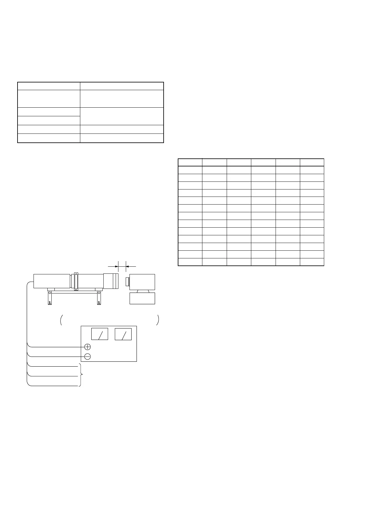
Fig. 5-1-12
Minipattern box
Below 3 cm
Camera
Camera
table
Red (+)
Black (–)
Yellow (SENS +)
White (SENS –)
Black (GND)
Need not connected
Regulated power supply
Output voltage : Specified voltage ±0.01Vdc
Output current : more than 3.5A
Address Data Address Data Address Data
14 36 21 20 90 00
15 48 22 BA 91 00
16 DA 23 46 92 00
17 DF 24 0A 93 00
18 16 25 00 94 00
19 00 88 00 95 00
1A 00 89 00 96 00
1B 00 8A 00 97 00
1C 00 8B 00 98 00
1D 00 8C 00 99 00
1E 00 8D 00 9A 00
1F 00 8E 00 9B 00
20 20 8F 00
Adjusting method:
1) Install the minipattern box so that the distance between it
and the front of lens of the camera is less than 3cm.
2) Make the height of minipattern box and the camera equal.
3) Check the output voltage of the regulated power supply is
the specified voltage ± 0.01 Vdc.
4) Check that the center of Siemens star chart meets the center
of shot image screen with the zoom lens at TELE end and
WIDE end respectively.
5) Select page: 0, address: 01, and set data: 01.
6) Select page: 5, address: F1, and set data: FF.
7) Select page: D, address: 63, set data: 40, and press the PAUSE
button of the adjusting remote commander.
8) Perform “ Data setting during camera system adjustment”.
(Refer to page 5-13)
9) Check that the data on page: F, addresses: 14 to 25, 88 to 9B
are initial values (See table below).
10) Select page: 6, address: 01, set data: 13, and press the PAUSE
button.
11) Select page: 6, address: 01, set data: 27, and press the PAUSE
button. (The flange back adjustment is performed and the
adjustment data is stored in page: F, address: 14 to 25, 88 to
9B)
12) Select page: 6, address: 02, and check that the data is “01”.
Processing after completion of adjustment:
1) Select page: 6, address: 01, set data: 00, and press the PAUSE
button of the adjusting remote commander.
2) Select page: 5, address: F1, and set data: 00.
3) Select page: D, address: 63, set data: 00, and press the PAUSE
button.
4) Release the data setting performed at step 8).
(Refer to page 5-13)
5) Select page: 0, address: 01, and set data: 00.
6) Perform “Flange Back Check”.
1. Flange Back Adjustment
(Using the minipattern box)
The inner focus lens flange back adjustment is carried out auto-
matically. In whichever case, the focus will be deviated during
auto focusing/manual forcusing.
Mode STILL
Subject Siemens star chart with ND filter
for minipattern box (Note 1)
Measurement Point Check operation on TV monitor
Measuring Instrument
Adjustment Page F
Adjustment Address 14 to 25, 88 to 9B
Note 1: Dark Siemens star chart.
Note 2: Check that the data of page: 6, address: 02 is “00”.
If not, turn the power of unit OFF/ON.
Preparations before adjustments:
The minipattern box is installed as shown in the following figure.
Note 3: The attachment lenses are not used.
Note 4: Take care not to hit the minipattern box when extending
the lens.
Specified voltage: The specified voltage varies according to the
minipatternbox, so adjustment the power sup
ply output voltage to the specified voltage
written on the sheet which is supplied with the
minipattern box.