6-1
NOTE:
• -XX and -X mean standardized parts, so they may
have some difference from the original one.
• Color Indication of Appearance Parts
Example:
KNOB, BALANCE (WHITE) . . . (RED)
↑↑
Parts Color Cabinet's Color
• Items marked “*” are not stocked since they are
seldom required for routine service. Some delay
should be anticipated when ordering these items.
• The mechanical parts with no reference number in
the exploded views are not supplied.
• Accessories are given in the last of the electrical
parts list.
SECTION 6
REPAIR PARTS LIST
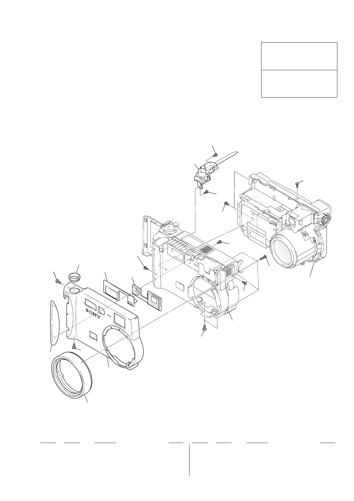
6-1. EXPLODED VIEWS
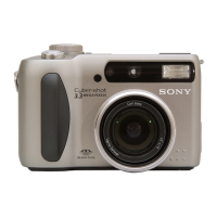
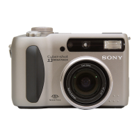
DSC-S70
The components identified by mark
0 or dotted line with mark 0 are
critical for safety.
Replace only with part number speci-
fied.
Les composants identifiés par une
marque 0 sont critiquens pour la
sécurité.
Ne les remplacer que par une pièce
portant le numéro spécifié.
Ref. No. Part No. Description RemarkRef. No. Part No. Description Remark
6-1-1. FRONT PANEL SECTION
4
5
6
7
4
3
4
2
1
4
4
4
10
8
4
8
9
4
8
Front cabinet
section (See page 6-2)
Rear cabinet
section
(See page 6-3)
1 3-060-265-01 RING, ORNAMENTAL
2 3-060-261-02 PANEL (FRONT), ALUMINUM
3 3-060-262-01 GRIP
4 3-968-729-71 SCREW (M2), LOCK ACE, P2
5 3-060-266-01 ESCUTCHEON
6 3-060-264-01 WINDOW, STROBOSCOPE
7 3-060-263-01 WINDOW
8 3-914-366-01 SCREW (DIA. 1.7X4), PRECISION
9 1-418-985-11 SWITCH BLOCK, CONTROL (MODE SW)
10 3-060-271-01 SCREW (M1.7X7)