58
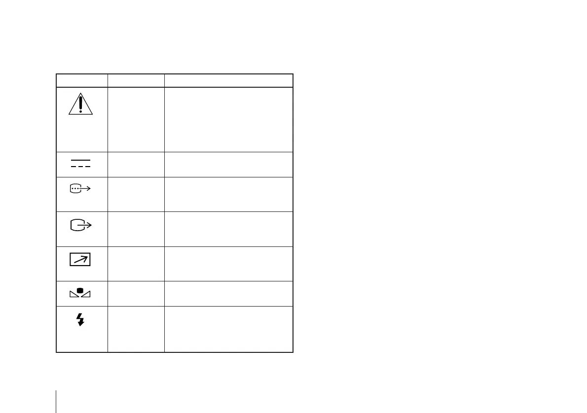
Symbols on the unit
Symbol Location This symbol indicates
Top This symbol is intended to alert the
user to the presence of important
operating and maintenance
(servicing) instructions in the
literature accompanying the
appliance.
Rear panel This symbol indicates that a direct
current (DC) is input.
Rear panel The connector that outputs RGB
signals and their respective sync
signals.
Rear panel The connector that outputs
composite video signals from the
camera module.
Rear panel The connector to which a remote
control signal is input from a
remote control unit.
Rear panel The button for setting the
automatic white balance.
Rear panel The connector that inputs a trigger
signal from a flash slave unit.
The button for activating the flash
when in the flash mode.